
Broadband Optical Phase Detection and Phase Noise Removal with an Optical Resonator

a phase noise detection and optical resonator technology, applied in the field of phase noise detection and removal apparatus, can solve problems such as interference with light, and achieve the effect of reducing the linewidth of the resonator and reducing the cutoff of low pass phase noise detection

Active Publication Date: 2013-08-29
RWTH AACHEN UNIVERSITY
View PDF3 Cites 15 Cited by
  • Summary
  • Abstract
  • Description
  • Claims
  • Application Information

AI Technical Summary

Benefits of technology

The patent describes a method for detecting phase noise in a laser using a resonator and a waveguide. The resonator is designed to store optical energy for a time and to track slowly varying phase noise with a certain time delay. The system is equivalent to an imbalanced interferometer in its functionality, and the resonator can be detuned to effectively cancel out phase noise. The method can be applied to both fiber and free space optics, and can be used to measure phase noise frequencies outside the resonator linewidth. The technical effects of this invention include improved accuracy in measuring phase noise and reduced interference with other laser frequencies.

Problems solved by technology

Light from the resonator couples back to the waveguide, and interferes with light in the waveguide (or fiber or free space beam) that did not get coupled into the resonator.

Method used


Image

  • Broadband Optical Phase Detection and Phase Noise Removal with an Optical Resonator
  • Broadband Optical Phase Detection and Phase Noise Removal with an Optical Resonator
  • Broadband Optical Phase Detection and Phase Noise Removal with an Optical Resonator

Examples


Embodiment Construction

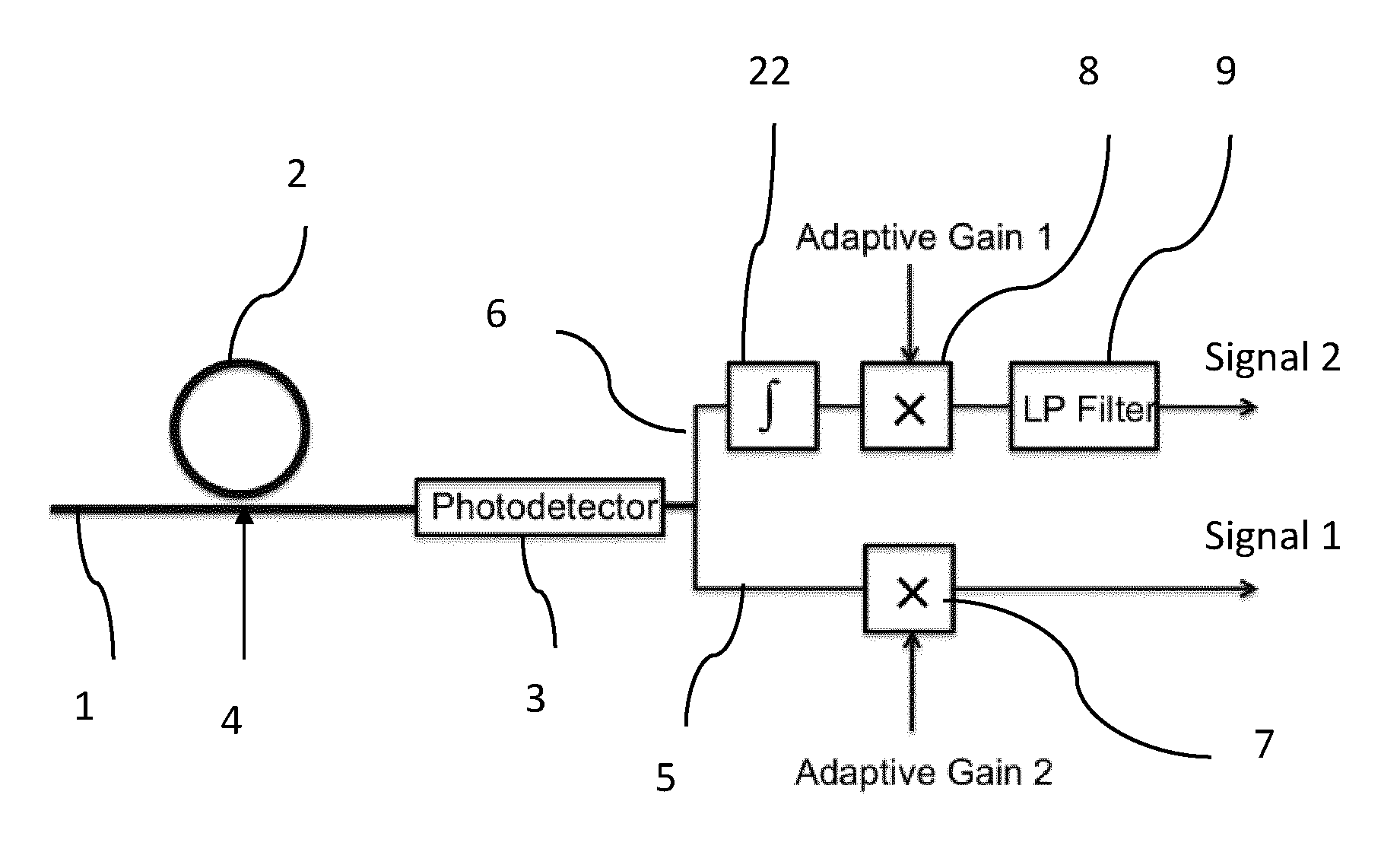
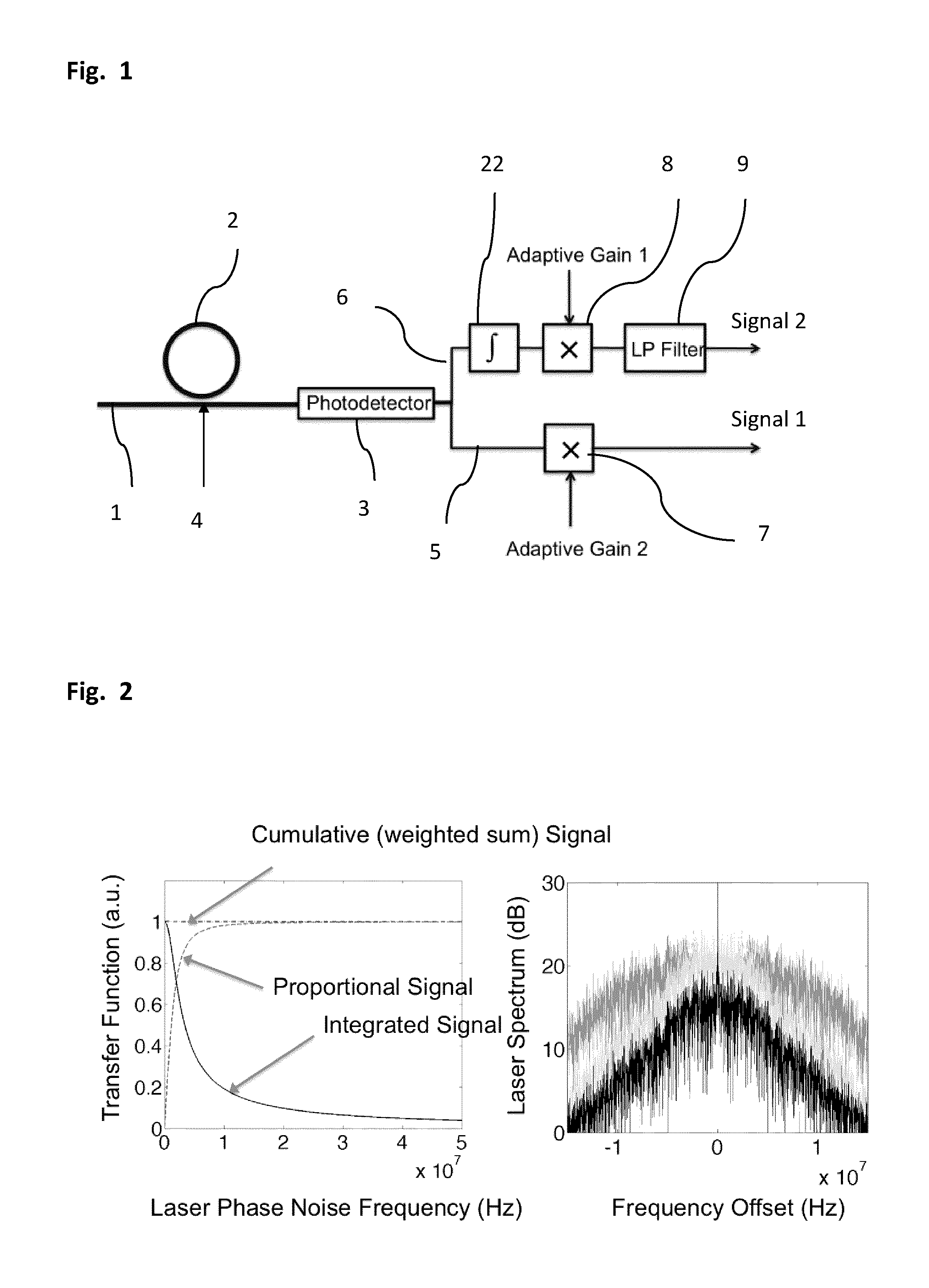
[0024]In FIG. 1 two signals are generated, one corresponding to the integrated optical output power of the waveguide coupled resonator and the other to a proportional, non-integrated signal.

[0025]Optionally, the two signals can be independently rescaled, with a gain that can be set by design, adjusted depending on resonator characteristics (for example according to a chip dependent quality factor or a chip dependent resonator to waveguide coupling strength) or dynamically adjusted with a control system, for example to account for laser power variations, slight resonator detuning etc. A control system is also typically needed to align the laser center frequency with the resonator resonance, either by tuning the laser or the resonator, or both. This relative alignment can be monitored for example by measuring the ratio of the optical power in the system before and after the resonator. The former requires an additional photodetector, while the latter can be measured either with an addi...


PUM


Abstract

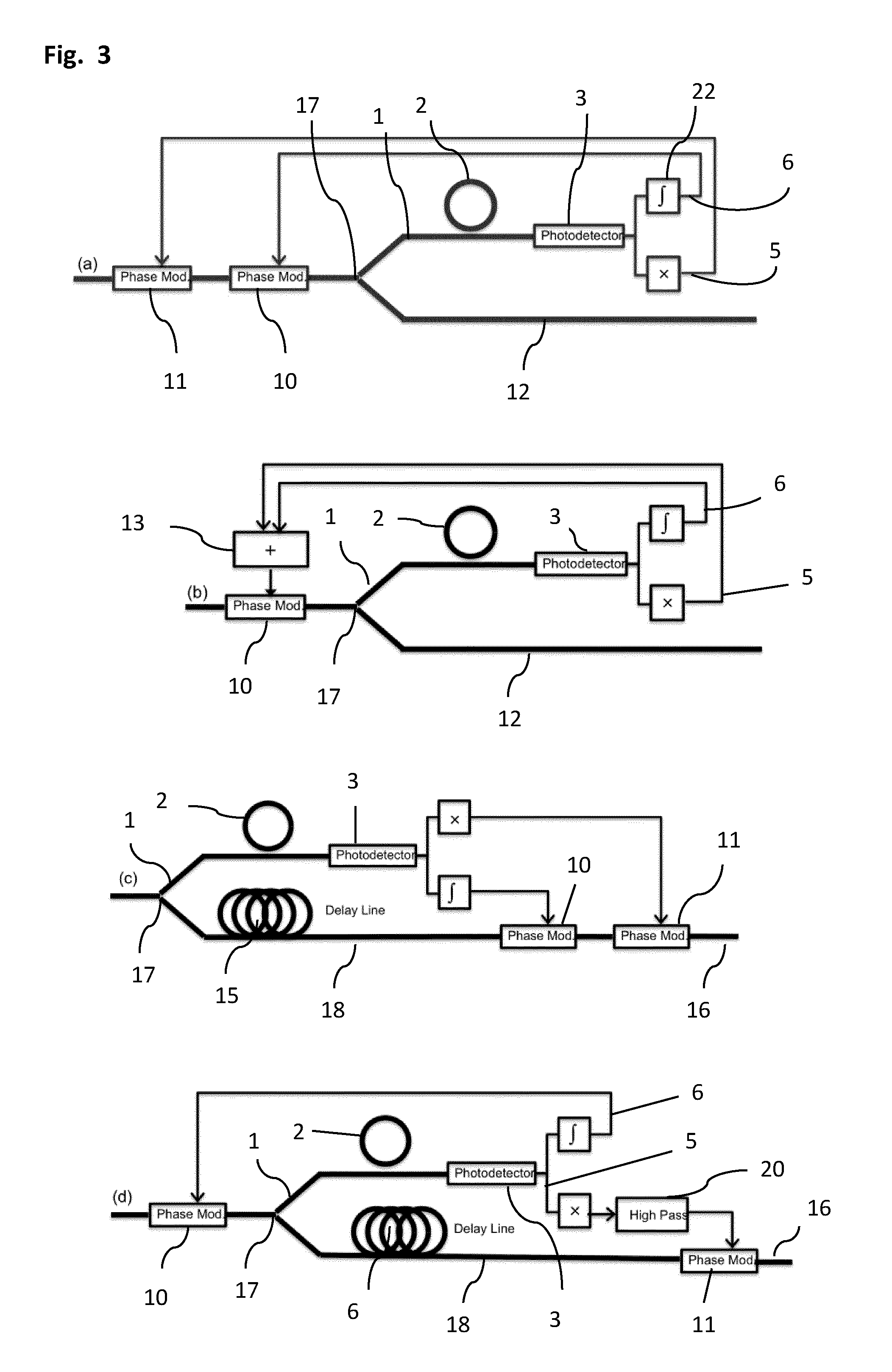
A phase noise detection apparatus comprises a laser beam, an optical resonator coupled thereto at a coupling point and a photodetector receiving light from the laser beam. The laser beam and the resonator coupled thereto convert phase noise of light transported by the laser beam prior to the coupling point into intensity noise of light transported by the laser beam thereafter. Intensity noise is converted into an electrical signal by the photodetector. The electrical signal is sent through a first signal path and a second signal path such that the first signal path transports a signal substantially proportional to the intensity noise, which is integrated in an integrator in the second path. Relative gain of the two signal paths can be adjusted and the overall gain of the signal path is preferably such that the optical phase modulator at least partially cancels said phase noise in the optical domain.

Description

CROSS-REFERENCE TO RELATED APPLICATIONS[0001]This application is the U.S. National Phase of International Application No. PCT / EP2011 / 067936, filed Oct. 13, 2011, claiming benefit of U.S. Provisional Patent Application No. 61 / 393,170, filed Oct. 14, 2010, U.S. Provisional Patent Application No. 61 / 437,673, filed Jan. 30, 2011, and U.S. Provisional Patent Application No. 61 / 442,179, filed Feb. 12, 2011, the contents of which are hereby incorporated by reference in their entirety as part of the present disclosure.FIELD OF THE INVENTION[0002]The present invention relates to a phase noise detection and removal apparatus.BACKGROUND OF THE INVENTION[0003]Laser phase noise is an important metric that can drive the performance of systems ranging from instrumentation to communication systems. Opto-electronic systems reducing laser phase noise are an ongoing development topic. In particular, achieving the performance of high performance bench top lasers by cleaning up the output of cheap and c...

Claims


Application Information

Patent Timeline
IPC IPC(8): H03L7/04H04B10/58H04B10/60
CPCH01S3/005H03L7/04H04B10/60H04B10/58H04B10/615H04B10/67H04B10/697H01S3/0085
Inventor WITZENS, JEREMY
Owner RWTH AACHEN UNIVERSITY
Learn More