
Light-diffusing ink composition and light guide panel using same

a technology of ink composition and light guide panel, which is applied in the direction of planar/plate-like light guide, lighting and heating apparatus, instruments, etc., can solve the problems of monotonous surface light, inability to produce aesthetically pleasing light, and limit the application of light guide panel to various fields besides the backlight unit, so as to reduce the number of components and reduce product thickness and weight

Inactive Publication Date: 2013-09-05
KSCB
View PDF2 Cites 15 Cited by
  • Summary
  • Abstract
  • Description
  • Claims
  • Application Information

AI Technical Summary

Benefits of technology

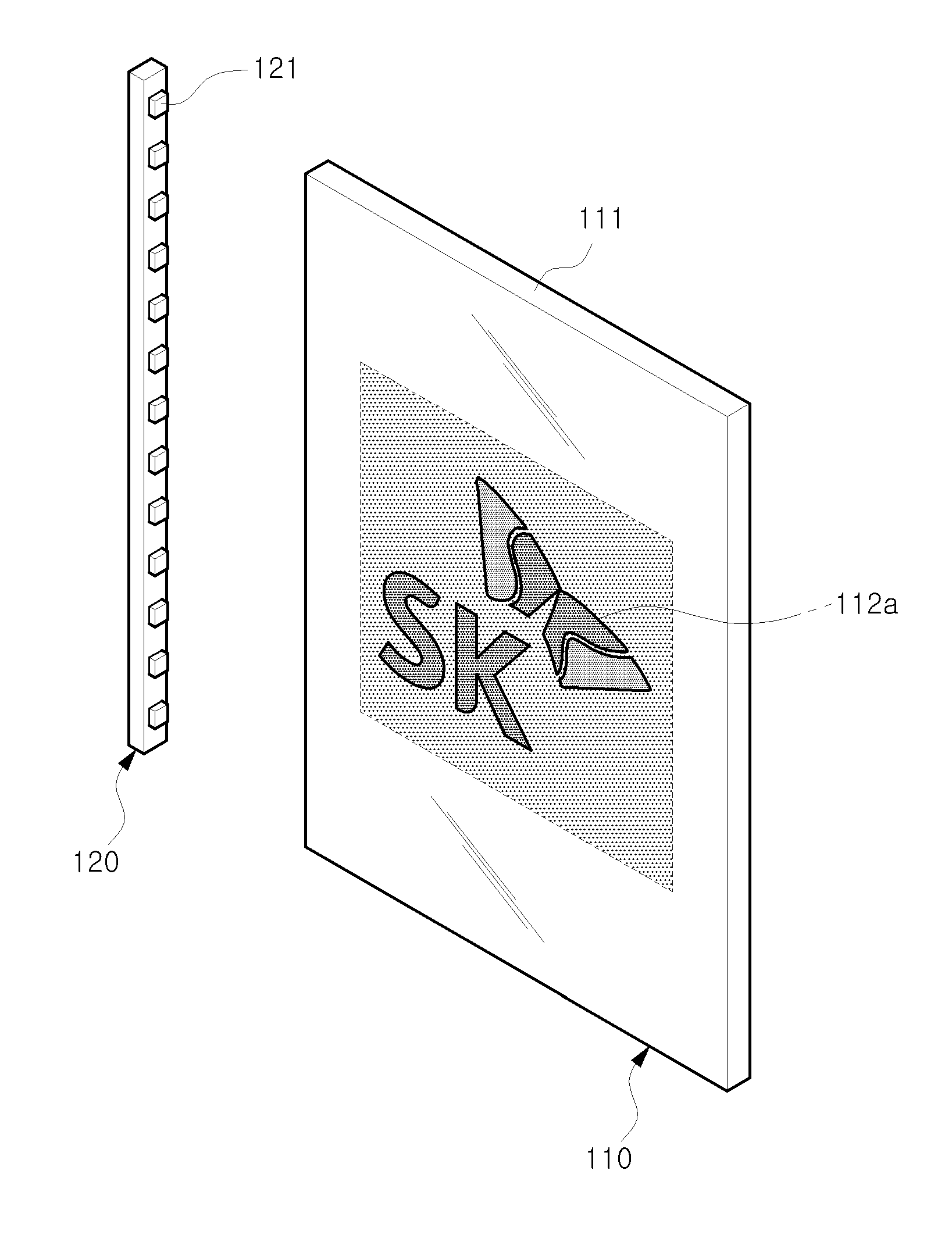
The invention is a light-diffusing ink composition and a light guide panel that can convert light from a light source into a crystal light pattern, producing aesthetics and sensuous light. The composition can be used to create colored crystal patterns, resulting in a mix of color and the light source. The invention can also allow for the creation of display panels with a desired design, without adding a separate image sheet, reducing the number of components and product weight. These panels can be used for decorative plates, signboards, billboards, and the like. Overall, the invention provides an aesthetically pleasing and beautiful design through the crystal light pattern.

Problems solved by technology

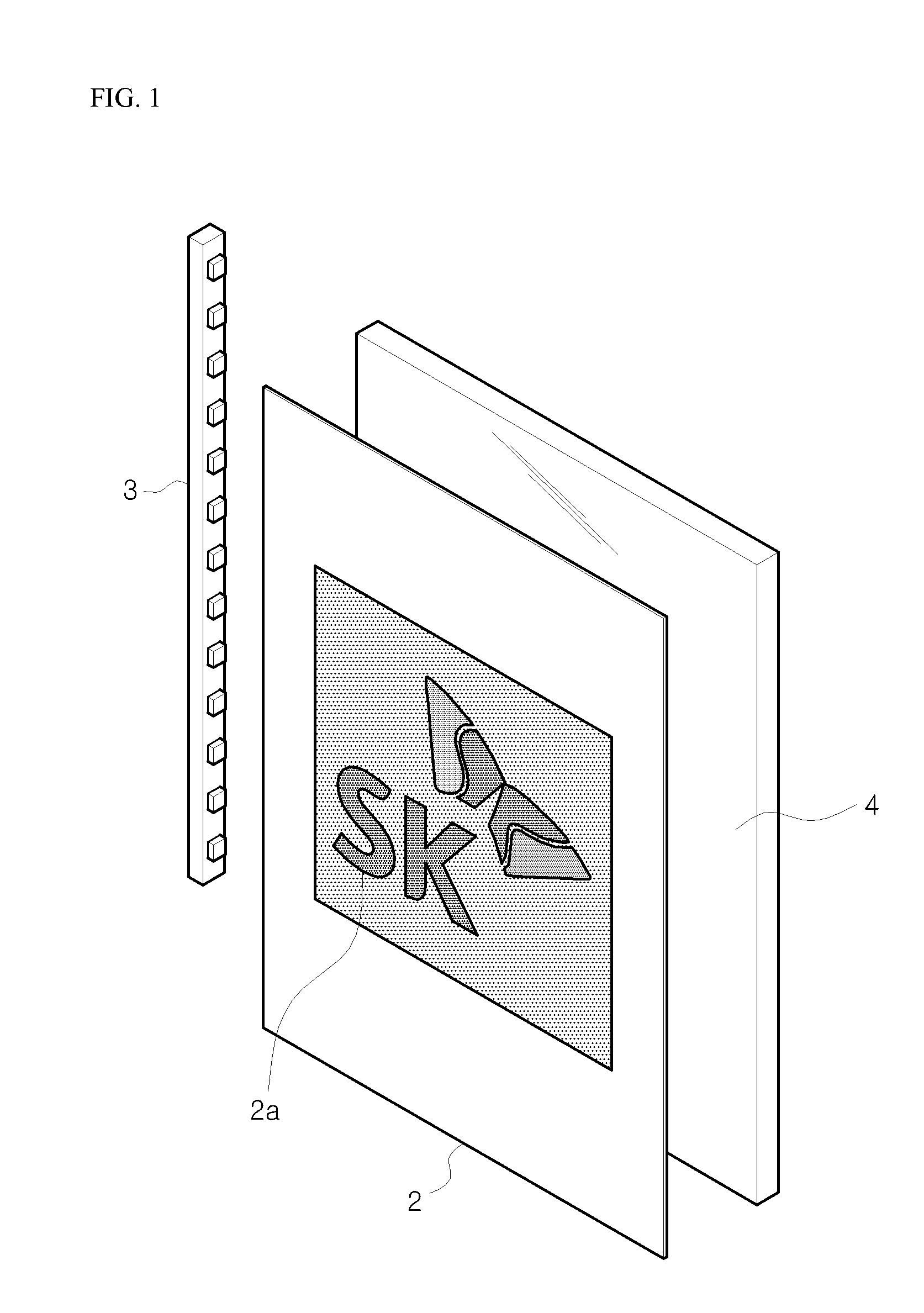
However, since the light guide panel manufactured by laser machining simply emits light from the light source in the form of surface light with the same color as the light emitted from the light source 3, the surface light becomes monotonous and is not aesthetically pleasing.
However, such a light guide panel using the light-diffusing ink simply scatters / reflects light of the light source at a portion on which the light-diffusing ink is printed, with the same color and uniform brightness, whereby the light guide panel itself cannot output aesthetically pleasing light.
Although the light-diffusing ink generally improves brightness, there is a limit in application of the light guide panel to various fields besides the backlight unit.

Method used


Image

  • Light-diffusing ink composition and light guide panel using same
  • Light-diffusing ink composition and light guide panel using same
  • Light-diffusing ink composition and light guide panel using same

Examples


Embodiment Construction

Example 2Example 1Example 2RemarksA-2130303030Acrylic resin(molecular weight:120,000)(Rohm & Haas)Isophorone30303030Ketone Solvent(boiling point: 210° C.)Butyl carbitol acetate23.623.623.623.6Ester Solvent(boiling point: 240° C.)BYK-0520.40.40.40.4Silicone antifoamingagent (BYK)G-4100.50.50.50.5Silicone leveling agent(Tego)BYK-20080.50.50.50.5Acrylic dispersant(BYK)PMMA beads15(average particle size: 15 μm)PMMA beads15(average particle size: 20 μm)PMMA beads15(average particle size: 2 μm)Silicone beads15(average particle size: 2 μm)Total100100100100

[0067]Further, color-differences (L, a, b), total light transmittance, and haze were measured using a color-difference meter and a haze meter with regard to the samples prepared in Examples 1 and 2 and Comparative Examples 1 and 2, and results are shown in Table 2. The results shown in Table 2 are the values before the light source was turned on, and crystal light was obtained at a total transmittance of 40 or more, an L value of 50 or le...


PUM

PropertyMeasurementUnit
particle sizeaaaaaaaaaa

Abstract

The present invention relates to a light-diffusing ink composition and to a light guide panel and display unit using same, wherein the light-diffusing ink composition comprises: an ink binder made of one or more selected from a group consisting of acrylic resin and polyvinyl chloride (PVC) copolymer; polymethylmethacrylate (PMMA) particles for forming a crystal optical pattern; and a solvent for ink. According to the present invention, light from a light source is converted into a crystal optical pattern and outputted, thus producing aesthetic and sensuous light, and lighting with an aesthetic design can be achieved by means of the light guide panel using the composition.

Description

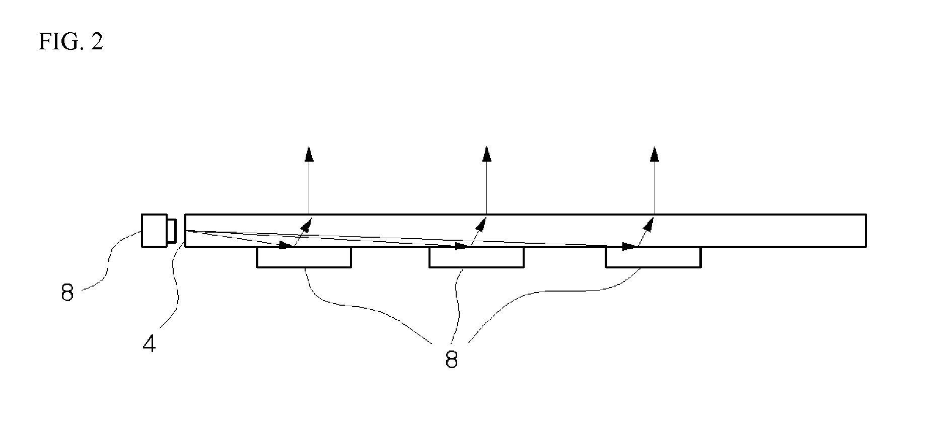
TECHNICAL FIELD [0001]The present invention relates to a light-diffusing ink composition, and more particularly, to an ink composition applied to a light guide panel and forming a light diffusive layer for light emitted from a light source, and a display unit using the same to display an image.BACKGROUND ART [0002]In general, a light guide panel is a part for receiving light from a light source and emitting light in the form of surface light having uniform brightness, and constitutes a backlight unit (BLU) of a liquid crystal display (LCD).[0003]Referring to FIGS. 1 and 2, when a light guide member 4 used in manufacture of the light guide panel, for example, a light guide plate or a light guide film made of plastic, glass or the like is carved to form a pattern 8 of scratches or dots on a surface of the light guide member by laser machining, the pattern 8 scatters / refracts / reflects light emitted from the light source 3, thereby allowing the light guide panel to emit illumination lig...

Claims


Application Information

Patent Timeline
Patent Type & Authority Applications(United States)
IPC IPC(8): F21V8/00
CPCC09D11/03C09D11/106G02B6/0043G02B6/0035G02B6/006
Inventor JEOUNG, SUNG-DONKANG, SANG-SOO
Owner KSCB
Learn More