Non-intrusive exhaust gas sensor monitoring

a technology of exhaust gas sensor and non-intrusive operation, which is applied in the direction of electrical control, process and machine control, instruments, etc., can solve the problems of reducing the likelihood of engine control based, reducing the accuracy of sensor degradation determination, and increasing emissions and/or reducing vehicle drivability, etc., to achieve less noise, improve the accuracy of sensor degradation determination, and improve the effect of fidelity

Active Publication Date: 2013-09-05
FORD GLOBAL TECH LLC
View PDF17 Cites 15 Cited by
  • Summary
  • Abstract
  • Description
  • Claims
  • Application Information

AI Technical Summary

Benefits of technology

[0006]The exhaust gas sensor time delay and line length may provide a robust signal that has less noise and higher fidelity than previous approaches. In doing so, the accuracy of the sensor degradation determination may be improved. In one example, the commanded change in lambda may be entry into or exit out of deceleration fuel shut-off (DFSO). During entry into DFSO, the engine may be commanded from stoichiometric operation to lean operation, and during exit out of DFSO, the engine may be commanded from lean operation to stoichiometric operation. As such, the exhaust gas sensor time delay and line length may be monitored during conditions that approximate lean-to-rich and rich-to-lean transitions to determine if any of the six discrete sensor degradation behaviors are present without intrusive excursions.
[0007]By determining degradation of an exhaust gas sensor using a non-intrusive approach with data collected during DFSO, exhaust gas sensor degradation monitoring may be performed in a simple manner. Further, by using the exhaust gas sensor output to determine which of the degradation behaviors the sensor exhibits, closed loop feedback control may be improved by tailoring engine control (e.g., fuel injection amount and / or timing) responsive to indication of the particular degradation behavior of the exhaust gas sensor to reduce the impact on vehicle drivability and / or emissions due to exhaust gas sensor degradation.

Problems solved by technology

Degradation of an exhaust gas sensor may cause engine control degradation that may result in increased emissions and / or reduced vehicle drivability.
Accordingly, accurate determination of exhaust gas sensor degradation may reduce the likelihood of engine control based on readings from a degraded exhaust gas senor.
However, these excursions may be restricted to particular operating conditions that do not occur frequently enough to accurately monitor the sensor.
Further, these excursions may increase engine operation at non-desired air / fuel ratios that result in increased fuel consumption and / or increased emissions.
Additionally, large amounts of background noise present in the collected samples may confound accurate determination of the sensor degradation.
The inventors herein have also recognized that, in such approaches which indicate sensor degradation based on comparing measured time delays and line lengths to expected responses, the expected response may be difficult to predict.
For example, changes in air mass, purge flow, and similar noises may contribute to inaccuracies in expected response determination and may result in reduced accuracy in sensor fault estimations.
In this way, sensor degradation may be at least partially based on comparing the response of the upstream sensor with the downstream sensor so that sensor faults may be identified even during conditions where an expected sensor response determination is inaccurate, e.g., due to changes in air mass, purge flow, and similar noises.

Method used


Image

  • Non-intrusive exhaust gas sensor monitoring
  • Non-intrusive exhaust gas sensor monitoring
  • Non-intrusive exhaust gas sensor monitoring

Examples


Embodiment Construction

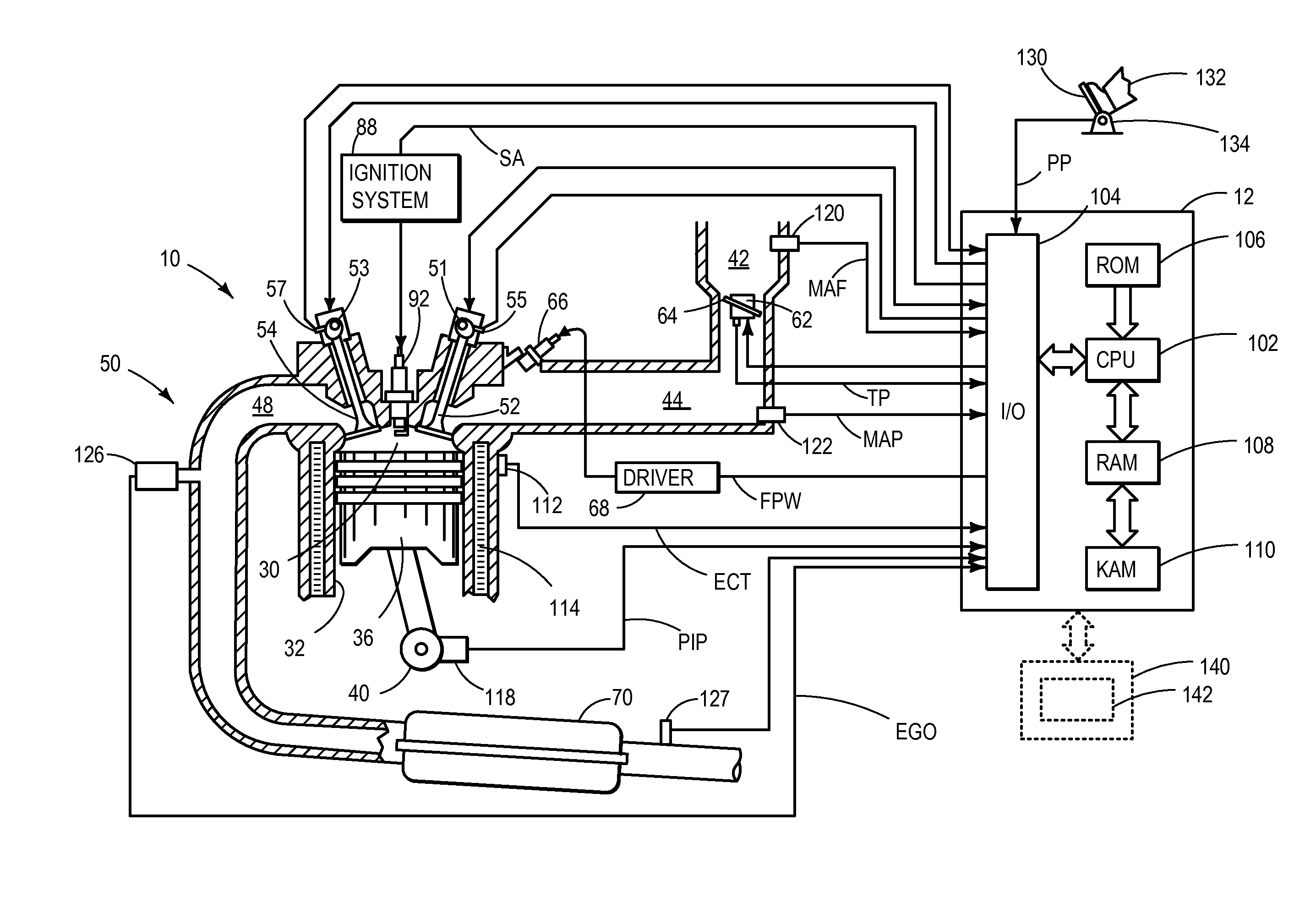
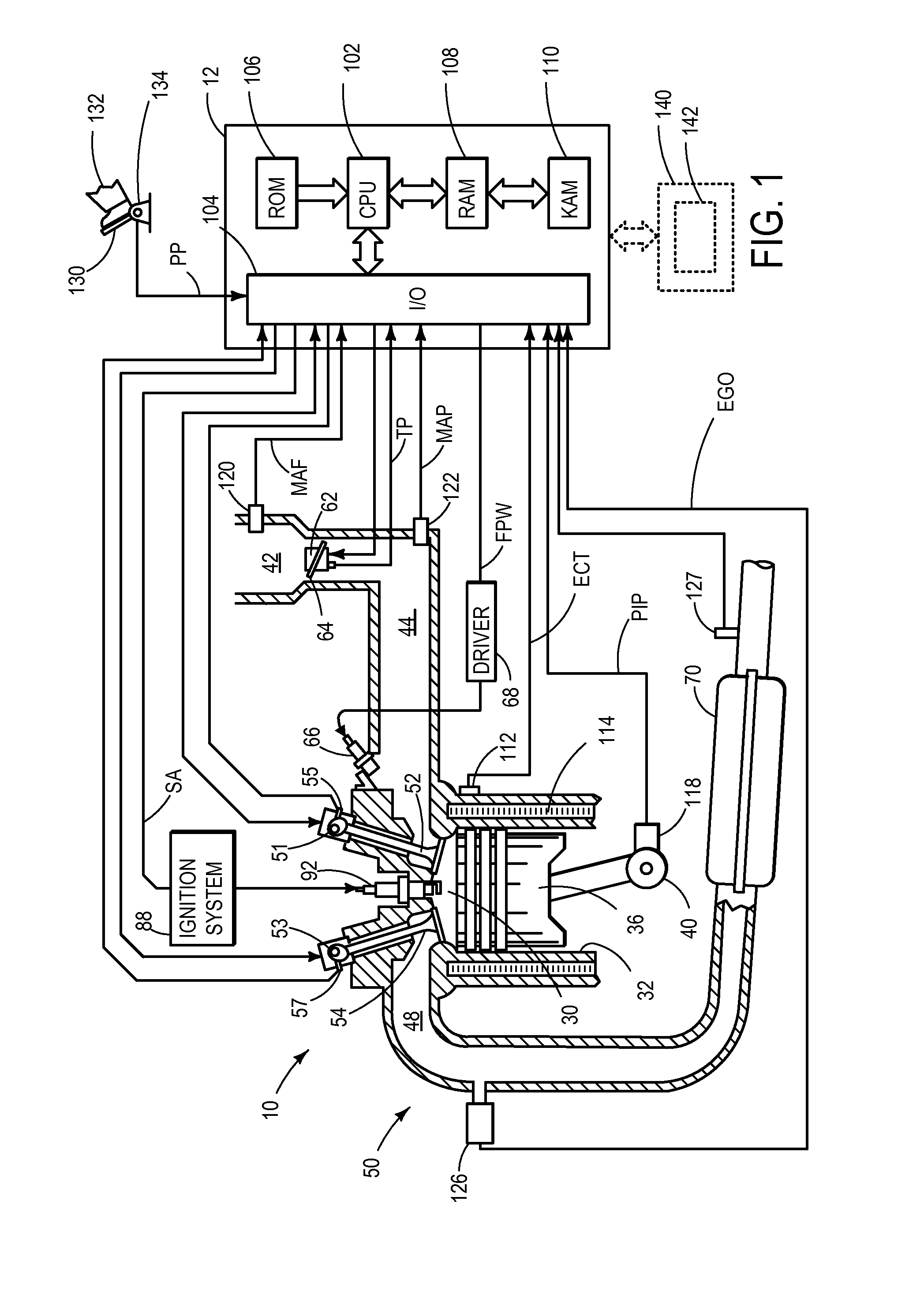
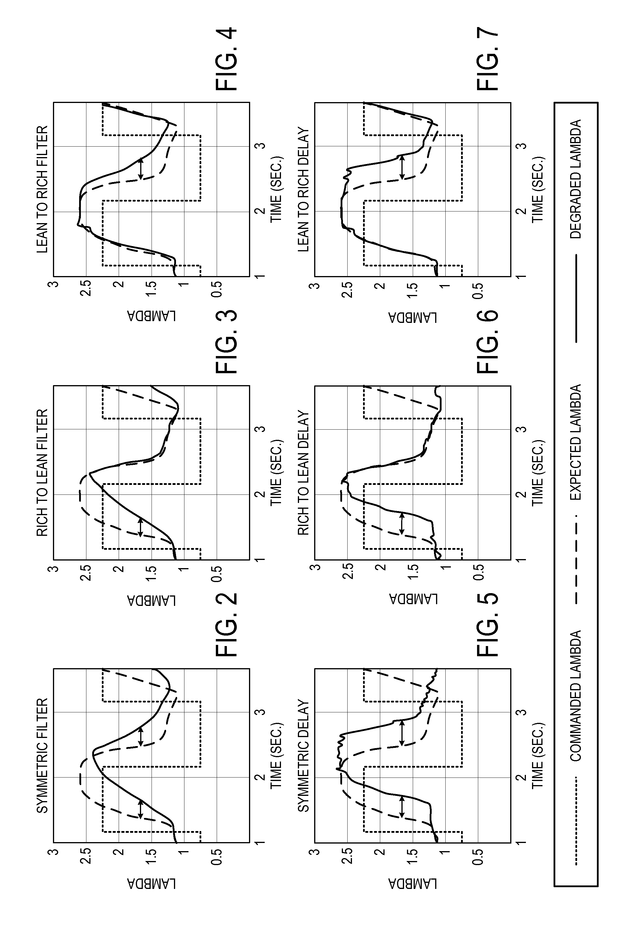
[0027]The following description relates to systems and methods for determining degradation of an exhaust gas sensor. More particularly, the systems and methods described below may be implemented to determine an upstream exhaust gas sensor degradation based on comparisons of an upstream sensor response with a downstream sensor response during commanded air / fuel ratio changes, e.g., entry into or exit out of deceleration fuel shut-off (DFSO). For example, if the downstream sensor responds before the upstream sensor then the upstream sensor may be degraded. Further, the systems and methods described below may be implemented to determine exhaust gas sensor degradation based on recognition of any one of six discrete types of behavior associated with exhaust gas sensor degradation. The recognition of the degradation behavior may be performed during entry into or exit out of DFSO to non-intrusively monitor exhaust gas sensor response during rich-to-lean and lean-to-rich transitions. Furthe...


PUM


Abstract

Systems and methods for monitoring an exhaust gas sensor coupled in an engine exhaust are provided. In one example approach, a method comprises indicating exhaust gas sensor degradation based on a downstream exhaust gas sensor responding before the upstream exhaust gas sensor during a commanded change in air-fuel ratio.

Description

CROSS REFERENCE TO RELATED APPLICATIONS[0001]The present application is a continuation-in-part of U.S. patent application Ser. No. 13 / 410,171, filed on Mar. 1, 2012, the entire contents of which are incorporated herein by reference for all purposes.BACKGROUND AND SUMMARY[0002]An exhaust gas sensor may be positioned in an exhaust system of a vehicle to detect an air / fuel ratio of exhaust gas exhausted from an internal combustion engine of the vehicle. The exhaust gas sensor readings may be used to control operation of the internal combustion engine to propel the vehicle.[0003]Degradation of an exhaust gas sensor may cause engine control degradation that may result in increased emissions and / or reduced vehicle drivability. Accordingly, accurate determination of exhaust gas sensor degradation may reduce the likelihood of engine control based on readings from a degraded exhaust gas senor. In particular, an exhaust gas sensor may exhibit six discrete types of degradation behavior. The de...

Claims


Application Information

Patent Timeline
Patent Type & Authority Applications(United States)
IPC IPC(8): F01N11/00
CPCF01N11/00F02D41/123F02D41/222F02D41/1454F02D41/1441
Inventor UHRICH, MICHAEL JAMESBANKER, ADAM NATHANKERNS, JAMES MICHAELMAKKI, IMAD HASSAN
Owner FORD GLOBAL TECH LLC
Why Eureka
Try Eureka