Magnetic modulation motor and electric transmission

Inactive Publication Date: 2013-09-12
DENSO CORP
View PDF0 Cites 31 Cited by
  • Summary
  • Abstract
  • Description
  • Claims
  • Application Information

AI Technical Summary

Benefits of technology

The present patent is about a motor that uses magnetic principles to generate motion. The motor has a special design that increases the strength and proof stress of the motor's rotor, which is important for its performance.

Problems solved by technology

However, the magnetic modulation motor as described above has the following issues.
This prevents the magnetic flux from passing through the part of the magnetic induction rotor and leads to generation of large loss.
This is why the magnetic induction rotor has a difficulty in casting soft magnetic material by a method such as aluminum die casting commonly used in well-known motors.
Thus, the magnetic induction rotor has a difficulty in ensuring mechanical rigidity and in being fixed to the rotary shaft, which causes a fundamental issue that proof stress is low.
However, in the case where the magnetic induction rotor is arranged at the most inner diameter side, there is a problem that preferable magnetic modulation is not established.
Then, even if the magnetic induction poles modulate magnetic flux of the magnet depending on the number of poles, the magnet stands in a path of the modulated magnetic flux going toward the armature or returning from it, and is an obstacle in the path of the modulated magnetic flux.
Therefore, the permanent magnet with strong magnetomotive force blocks the modulated magnetic flux over a widely-covered range, thereby disturbing the modulated magnetic flux.
This requires oil lubrication, thereby resulting in low transmission efficiency.
The configuration of the first rotary machine makes it difficult to downsize the first and second rotary machines (especially, the first rotary machine corresponding to the magnetic modulation motor).
This causes eddy current in the magnetic modulation element.
Therefore, this makes it difficult to: (i) support, by a metallic member, a plurality of soft magnetic materials forming the magnetic modulation element, or (ii) support the magnetic modulation element by a support member to which the plurality of soft magnetic materials are directly connected by welding or fastening.
However, the support structure uses resin or the like having a strength lower than metallic member, thereby being unable to resist high speed high vibration of an engine.
On the other hand, as described above, the magnetic modulation element is positioned in the path of magnetic flux going and returning between the armature and the field element, thereby causing generation of eddy current.
This generation of eddy current makes it difficult to support the magnetic modulation element by using a metallic member.
In addition, in the configuration disclosed in JP-B2-4505524, two inverters called as PDU (power drive unit) are required, and then, it is also difficult to realize two rotors as above-described in the second case in which the first and second rotary machines are radially arranged.
In such a non-synchronous machine, the armature and the field element, which differ from each other in the number of poles, are arranged adjacent to each other, thereby increasing magnetic interference between them so as to magnetically disturb each other.
This makes it impossible for the magnetic modulation element to cause operation of magnetic modulation.
This is why a rotary machine, in which the magnetic modulation element is located outside the armature and the field element, has not been proposed and put into practical use.
Therefore, even if the first field element is located between the first armature and the magnetic modulation element (this arrangement cannot be easily derived from related art), magnetic modulation action can effectively work.
Therefore, even if the field element is located between the first armature and the magnetic modulation element (this arrangement cannot be easily derived from related art), magnetic modulation action can effectively work.

Method used


Image

  • Magnetic modulation motor and electric transmission
  • Magnetic modulation motor and electric transmission
  • Magnetic modulation motor and electric transmission

Examples


first exemplary embodiment

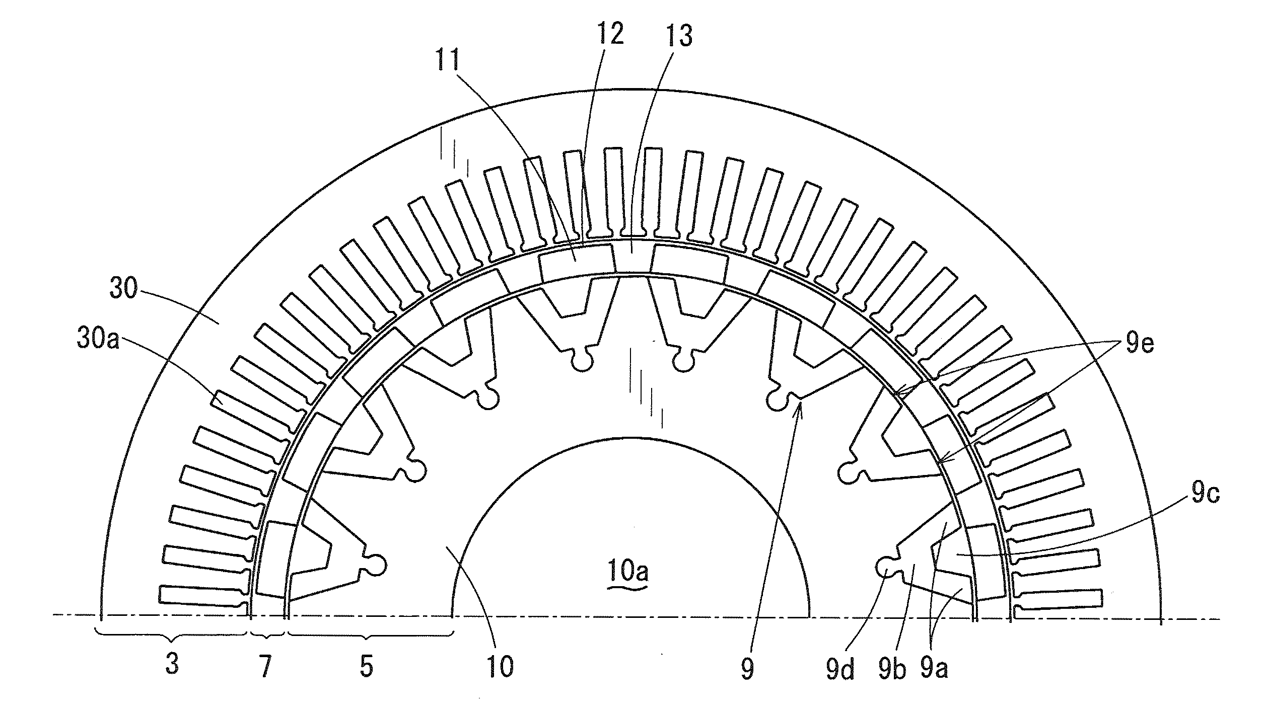
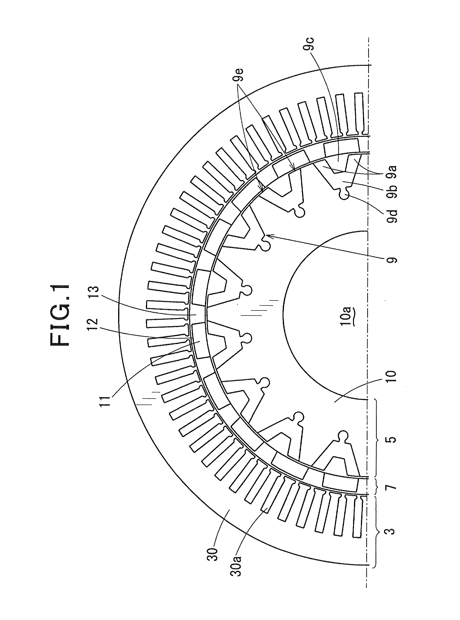
[0133]FIGS. 1 to 4 show a magnetic modulation motor (hereinafter referred to as “motor”) 1 according to a first exemplary embodiment of the present invention, which is mounted between an engine and a transmission in a hybrid vehicle.

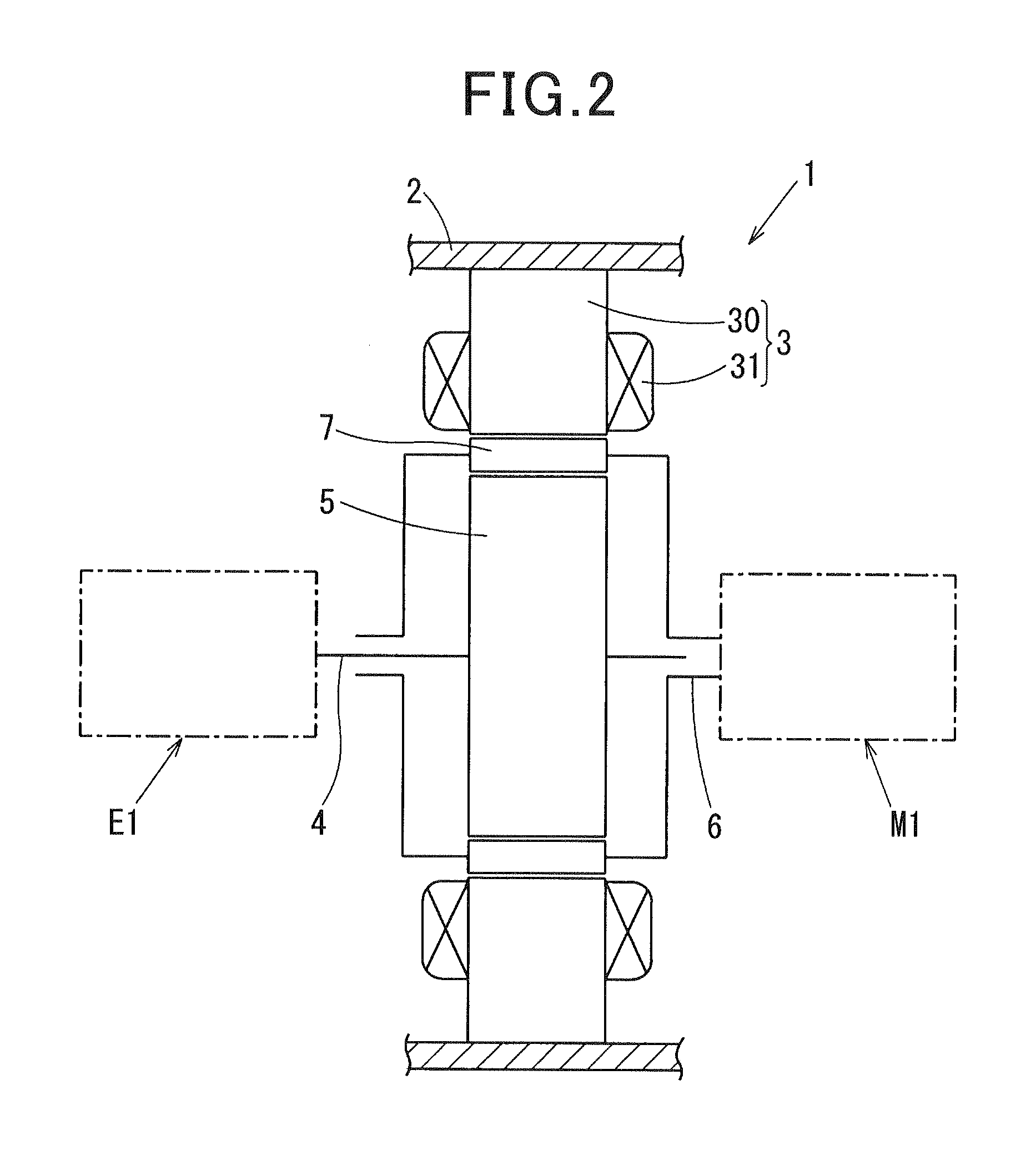
[0134]First, a configuration of the motor 1 is described. As shown in FIG. 2, the motor 1 includes a motor frame 2, an armature 3, a first rotary shaft 4, a magnetic induction rotor 5, a second rotary shaft 6, and a magnet rotor 7. The armature 3, the magnet rotor 7, and the magnetic induction rotor 5 are arranged in the order from the radially outer side to the radially inner side (center side) of the motor 1. The armature 3 is fixed to the motor frame 2. The first rotary shaft 4 is coupled with an output shaft of an engine E1, and is supported by the motor frame 2 in a rotatable manner via a bearing (not shown). The magnetic induction rotor 5 rotates integrally along with the first rotary shaft 4. The second rotary shaft 6 is coupled with an driven sha...

second exemplary embodiment

[0190]Referring to FIGS. 11, 12A and 12B, the second exemplary embodiment is described. In this embodiment, as shown in FIG. 11, a concave portion (recess or hollow portion) 13a is formed in the respective interpolar soft magnetic materials 13 of the magnetic induction rotor 5 described in the first exemplary embodiment.

[0191]As shown in FIG. 11, the concave portion 13a is formed in a surface of the respective interpolar soft magnetic materials 13 facing the magnetic induction rotor 5, i.e., an inner diameter face of the interpolar soft magnetic material 13 facing an outer diameter face of the magnetic induction rotor 5 via the gap between the magnet rotor 7 and the magnetic induction rotor 5. The concave portion 13a has a depth of approximately ⅔ of a thickness (i.e., a radial size) of the magnet rotor 7 and is formed into a taper shape in which an circumferential opening width is gradually widened from the deepest portion toward the inner diameter face of the magnet rotor 7.

[0192]...

third exemplary embodiment

[0197]Referring to FIGS. 13, 14A and 14B, the third exemplary embodiment is described. In the present embodiment, the magnetic induction rotor 5 is formed into a gear shape.

[0198]As shown in FIG. 13, the magnetic induction rotor 5 is configured by laminating a plurality of electromagnetic steel plates which are cut out in the form of a gear shape, and includes k tooth-shaped portions 5a which radially project toward the outside, where k is the number of tooth-shaped portions 5a. The k tooth-shaped portions 5a are circumferentially arranged at regular intervals, which form an entry and exit of magnetic flux for the magnetic path.

[0199]Next, a magnetic field analysis of the motor 1 according to the third exemplary embodiment is also performed under the same condition as the first exemplary embodiment. FIG. 14A shows a model configuration diagram of an analysis model of the motor 1 according to the present embodiment, and FIG. 14B shows a simulation result of the magnetic field analysi...


PUM


Abstract

A magnetic modulation motor includes an armature, a magnetic induction rotor, and a magnet rotor. The armature is provided with a multi-phase winding with m pole pairs. The magnetic induction rotor includes k magnetic paths. In the magnet rotor, 2n permanent magnets forming a polarity region with n pole pairs are separately and annularly placed. The armature, the magnet rotor, and the magnetic induction rotor are arranged in the order from a radially outer side to a radially inner side. In the magnetic induction rotor, the magnetic path has two ends projecting toward a magnetic flux entry and exit located at an outer diameter face of the magnetic induction rotor, and forms a magnetic flux path between the magnetic flux entry and exit. The magnet rotor includes magnetic flux penetration region magnetically penetrated by magnetic flux between each circumferentially adjacent two permanent magnets.

Description

CROSS-REFERENCE TO RELATED APPLICATION[0001]This application is based on and claims the benefit of priority from earlier Japanese Patent Application Nos. 2012-053227 filed Mar. 9, 2012, 2012-176329 filed Aug. 8, 2012, and 2012-200426 filed Sep. 12, 2012, the descriptions of which are incorporated herein by reference.BACKGROUND[0002]1. Technical Field[0003]The present invention relates to a magnetic modulation motor and an electric transmission suitable for use in a power device for hybrid vehicles which are driven by a mechanical power of an internal combustion and an electric power of a battery.[0004]2. Description of the Related Art[0005]As related art of a power transmission device for hybrid automobiles, there is a commonly used device which transmits power via a motor and a CVT (continuously variable transmission) between an output shaft of an internal combustion and an input shaft of a gear that switches between speed reduction and back-and-forth motion. Recently, new technolo...

Claims


Application Information

Patent Timeline
IPC IPC(8): H02K16/02
CPCH02K16/02H02K17/165H02K51/00H02K21/14H02K17/18
Inventor KUSASE, SHINKANAME, YOUSUKESAKURAI, NAOTO
Owner DENSO CORP
Why Eureka
Try Eureka