Structures and methods for splicing glass ribbon

Active Publication Date: 2013-09-12
CORNING INC
View PDF10 Cites 8 Cited by
  • Summary
  • Abstract
  • Description
  • Claims
  • Application Information

AI Technical Summary

Benefits of technology

[0007]Disclosed herein are various embodiments of structures and methods for splicing glass ribbon portions to one another as well as to other web materials, for example, leader/trailer materials. Throughout the disclosure the term “glass” is used for sake of convenience, but is representative of other like brittle materials, for example glass ceramics and ceramics, that may be formed into flexible ribbons≦about 0 3 mm thick, for example, 0.3 mm, 0.25 mm, 0.20 mm, 0.15 mm, 0.10 mm, 0.05 mm, 0.025 mm, 0.020 mm, 0.015 mm, and 0.010 mm. The structures and methods disclosed herein provide a manner of achieving, with glass, functions similar to those to which manufactures are accustomed to for polymer, paper, and metal web material systems. This reduces customer switching costs, increases yield of the process using flexible glass substrates by reducing the number of proc

Problems solved by technology

Use of polymer or metal substrates results in either reduced end device performance or increased cost.
The solutions for splicing common web materials such as polymer, paper, metal, and other webs, are not appropriate for glass because of the different material properties involved, notably the brittle nature of glass.
With respect to the splice joint itself, for example, the inventors found that the glass ribbon portions should be gapped apart from one another

Method used


Image

  • Structures and methods for splicing glass ribbon
  • Structures and methods for splicing glass ribbon
  • Structures and methods for splicing glass ribbon

Examples


example 1

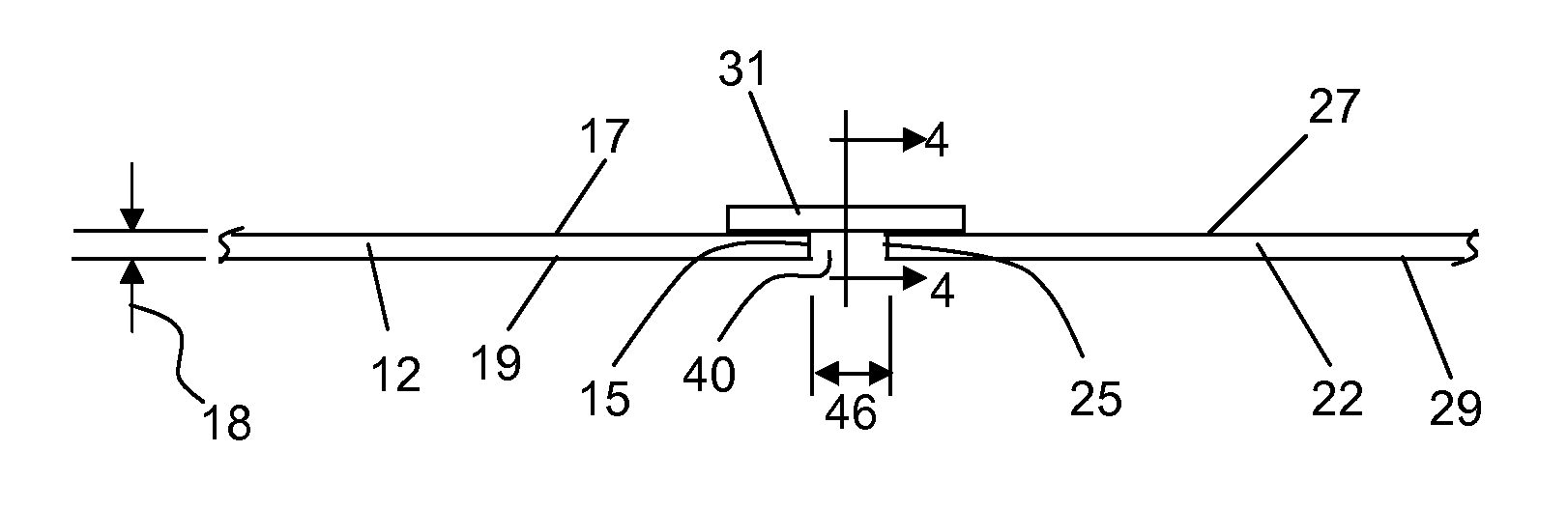
[0110]A splice member 31 having a thickness of 50 μm, a width of 250 mm, and a Young's modulus of 1 GPa, is applied to the major surfaces 17, 27, wherein gap 40 is 100 μm (corresponding to splice length). A 10 kgf (100 N) would produce a stress of 8 MPa, and a calculated strain of 0.8% (corresponding to a change in splice length of 0.8 μm).

example 2

[0111]The splice member 31 and gap 40 are the same as in Example 1, except the splice member 31 has half the thickness (i.e., 25 μm).

[0112]Particularly: thickness of 25 μm; width of 250 mm; Young's modulus of 1 GPa; and gap of 100 μm.

[0113]In this example, a 10 kgf would produce a stress of 16 MPa, and a calculated strain of 1.6% (corresponding to a change in splice length of 1.6 μm).

example 3

[0114]The splice member 31 and gap 40 are the same as in Example 1, except the splice member 31 has a lower modulus (i.e., 0.5 GPa).

[0115]Particularly: thickness of 50 μm; width of 250 mm; Young's modulus of 0.5 GPa; and gap of 100 μm.

[0116]In this example, a 10 kgf would produce a stress of 8 MPa, and a calculates strain of 1.6% (corresponding to a change in splice length of 1.6 nm).


PUM

PropertyMeasurementUnit
Weightaaaaaaaaaa
Fractionaaaaaaaaaa
Thicknessaaaaaaaaaa

Abstract

A glass ribbon (10) including a first glass-ribbon portion (12) and a second portion (22) separated from one another by a gap (40), and a splice joint (30) coupling the first glass-ribbon portion to the second portion. The splice joint includes a splice member (31) having a Young's modulus and cross sectional area so that when subject to a force of 20 kg the splice member under-goes an elongation of ≦20%. A filler material (80) may be disposed in the gap. Also, there are disclosed methods of splicing a glass ribbon, and preparing a coated glass ribbon for splicing. One embodiment of a method of splicing glass ribbon includes applying tape (70) to the glass ribbon, and cutting the glass ribbon together with the tape so as to create a free end in the glass ribbon. Before the glass ribbon is cut, a fracture line (75, 77) may be created in the glass ribbon wherein the tape is disposed across the fracture line. When preparing a coated glass ribbon, a separate tape member need not be applied before creating the fracture line or cutting the glass ribbon.

Description

[0001]This application claims the benefit of priority under 35 USC §119 of U.S. Provisional Application Ser. No. 61 / 418,094 filed on Nov. 30, 2010 the content of which is relied upon and incorporated herein by reference in its entirety.BACKGROUND[0002]1. Field[0003]The present invention relates to glass ribbons and, more particularly, to structures and methods for splicing portions of glass ribbons to one another or to leader / trailer materials.[0004]2. Technical Background[0005]There is interest in using glass in roll-to-roll fabrication of flexible electronic or other devices. Glass has several beneficial properties related to either the fabrication or performance of electronic devices. Currently these devices are being fabricated on polymer film or metal foil because a complete solution for the use of flexible glass does not exist. Use of polymer or metal substrates results in either reduced end device performance or increased cost. A more complete solution for the use of flexible...

Claims


Application Information

Patent Timeline
IPC IPC(8): C03B33/02
CPCB65H19/1852B65H2301/4621B65H2301/4631Y10T428/18C03B33/0235C03B33/074C03B33/02B65H2801/61Y02P40/57B65H2301/5132Y10T83/0405B65H2301/46222C03B33/037
Inventor GARNER, SEAN MATTHEWMERZ, GARY EDWARDTOSCH, JOHN EARL
Owner CORNING INC
Why Eureka
Try Eureka