Tandem organic electroluminescence device

Inactive Publication Date: 2013-09-19
IDEMITSU KOSAN CO LTD
View PDF0 Cites 17 Cited by
  • Summary
  • Abstract
  • Description
  • Claims
  • Application Information

AI Technical Summary

Benefits of technology

[0027]According to the invention, it is possible to provide a device which has a high

Problems solved by technology

Of these methods, only a few methods can obtain white emission by using one emitting material.
However, since all emission color is fluorescent color, these devices have low luminous efficiency. FIG. 7 shows the relationship between the color tempera

Method used


Image

  • Tandem organic electroluminescence device
  • Tandem organic electroluminescence device
  • Tandem organic electroluminescence device

Examples


example 1

(1) Fabrication of an Organic EL Device

[0233]The organic EL device according to Example 1 was fabricated as follows.

[0234]A glass substrate (manufactured by Geomatics Co.), measuring 25 mm×75 mm×1.1 mm thick, with an ITO transparent electrode (anode) was subjected to ultrasonic cleaning in isopropyl alcohol for 5 minutes and then to UV ozone cleaning for 30 minutes.

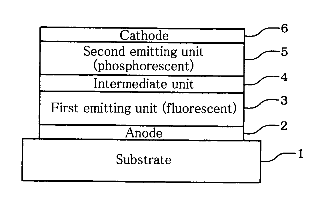
[0235]On this glass substrate, a first emitting unit was formed.

[0236]The cleaned glass substrate with transparent electrode lines was mounted on a substrate holder in a vacuum deposition device. Compound HI1 was stacked on the surface where the transparent electrode lines were formed so as to cover the transparent electrode by resistance heating deposition. By this, a hole-injecting layer with a thickness of 50 nm which is in adjacent with the anode was formed.

[0237]On this hole-injection layer, compound HT1 was stacked by resistance heating deposition. As a result, a hole-transporting layer having a thickness of 45 nm w...


PUM


Abstract

A tandem organic electroluminescence device including a first emitting unit (3), an intermediate unit (4) and a second emitting unit (5) being stacked between opposing electrodes (2) and (6) the first emitting unit (3) including a blue fluorescent dopant and a red fluorescent dopant and the second emitting unit (5) including a red phosphorescent dopant and a green phosphorescent dopant.

Description

TECHNICAL FIELD[0001]The invention relates to a tandem organic electroluminescence device, in particular, to a warm color (having a low color temperature) white organic electroluminescence device.BACKGROUND ART[0002]In recent years, development of a white color organic electroluminescence device (organic EL device) has been actively conducted due to its application as a mono-color display apparatus, illumination such as backlight, a full-color display device using a color filter or the like. In particular, when a white organic EL device is used in illumination, a white organic EL device is required to have a high luminous efficiency which is equal to or higher than the luminous efficiency of a fluorescent organic EL device. Many methods for obtaining white emission by an organic EL device are known. Of these methods, only a few methods can obtain white emission by using one emitting material. Normally, two or three types of emitting materials are caused to emit light simultaneously ...

Claims


Application Information

Patent Timeline
IPC IPC(8): H01L51/50
CPCC09K11/06C09B3/14C09K2211/1011C09K2211/1029H01L27/3209H01L51/504H01L51/5044H01L2251/5376H05B33/10C09B6/00C09B57/00C09B57/001C09B57/008C09B1/00C09B3/78C09B3/02C09K2211/1007H10K59/32H10K50/131H10K50/13H10K2101/27
Inventor ARAKANE, TAKASHINISHIMURA, KAZUKIFUKUOKA, KENICHIKUMA, HITOSHIJINDE, YUKITOSHI
Owner IDEMITSU KOSAN CO LTD
Why Eureka
Try Eureka