Insert

a technology of inserts and inserts, applied in the field of inserts, can solve the problems of increasing the frequency of insert replacement during work, increasing the material cost, etc., and achieve the effects of reducing work cost, enhancing the strength of the cutting edge portion formed across the convex, and improving the work efficiency of cutting work

Active Publication Date: 2013-09-19
DAISHOWA SEIKI CO LTD
View PDF57 Cites 8 Cited by
  • Summary
  • Abstract
  • Description
  • Claims
  • Application Information

AI Technical Summary

Benefits of technology

[0014]By forming the rake face in a shape having a convex as in the above configuration, a predetermined rake angle can be obtained without the necessity of fixing the insert at an angle with respect to the rotary cutting tool.
[0015]Also, since the convex for formation of the rake face is formed with the thickness of the convex added to the thickness of the insert, the strength of the cutting edge portion formed across the convex is enhanced.
[0016]Moreover, since the cutting edge portion is formed on each side of the insert having a polygonal shape, one insert can be used repeatedly by the number of cutting edge portions. As a result, the work efficiency of the cutting work improves, permitting reduction in work cost.

Problems solved by technology

This causes a drawback of increasing the material cost particularly when the insert is formed of sintered metal, etc.
This increases the frequency of insert replacement during working.

Method used


Image

  • Insert
  • Insert
  • Insert

Examples


first embodiment

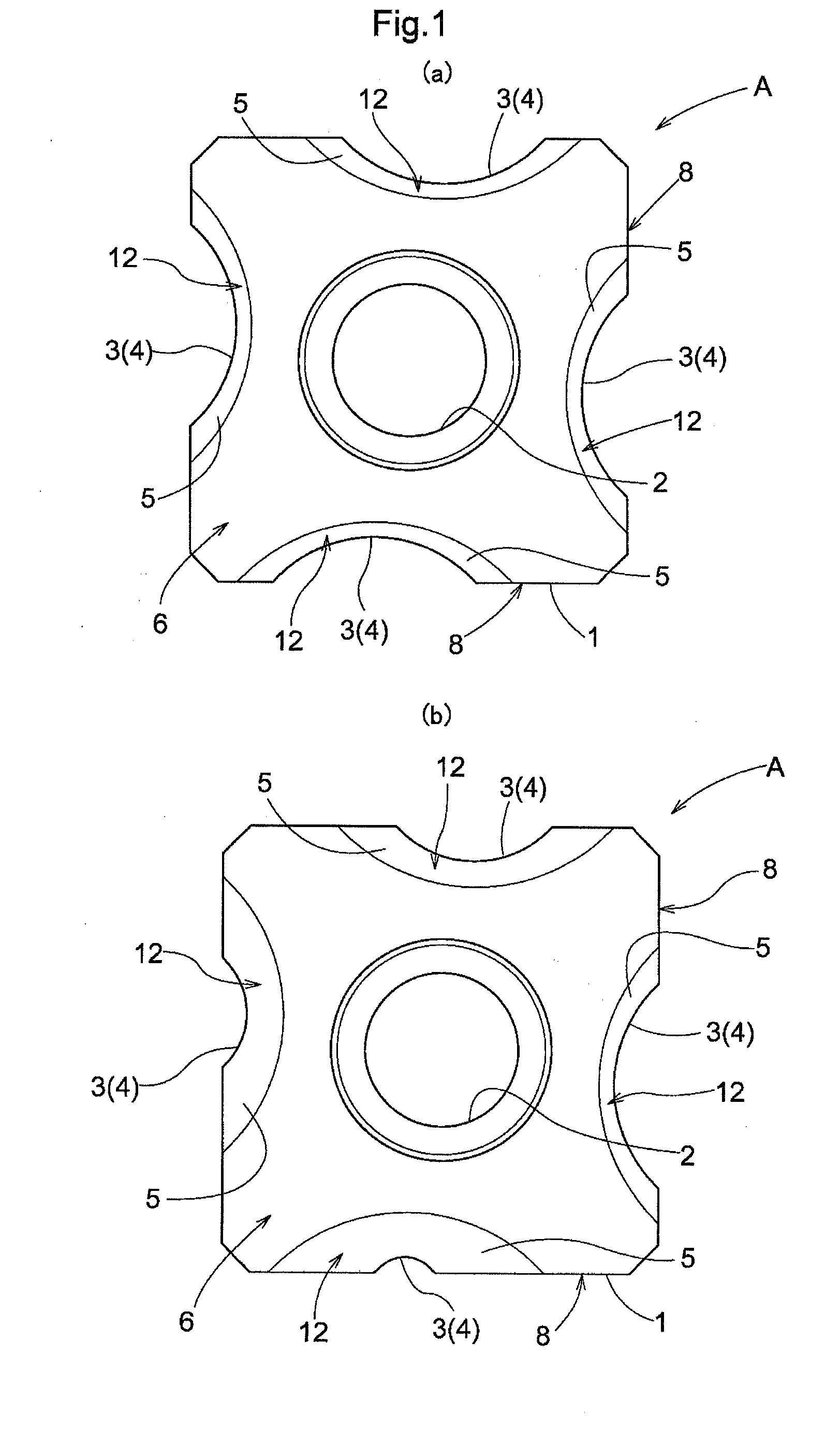
[0036]FIGS. 1 and 2 show examples of an insert of the present invention. An insert A is fixed to a rotary cutting tool C for chamfering a corner of a material D to be cut into a round shape (curved shape) as shown in FIG. 7. The insert A is formed using hard metal, etc., for example.

[0037]The insert A has a base 1 formed into a generally square shape as viewed from top. One fixation hole 2 for fixing the base 1 to the rotary cutting tool C is provided in the center of the base 1. Four cutting edge portions 3 are provided at the sides of the base 1.

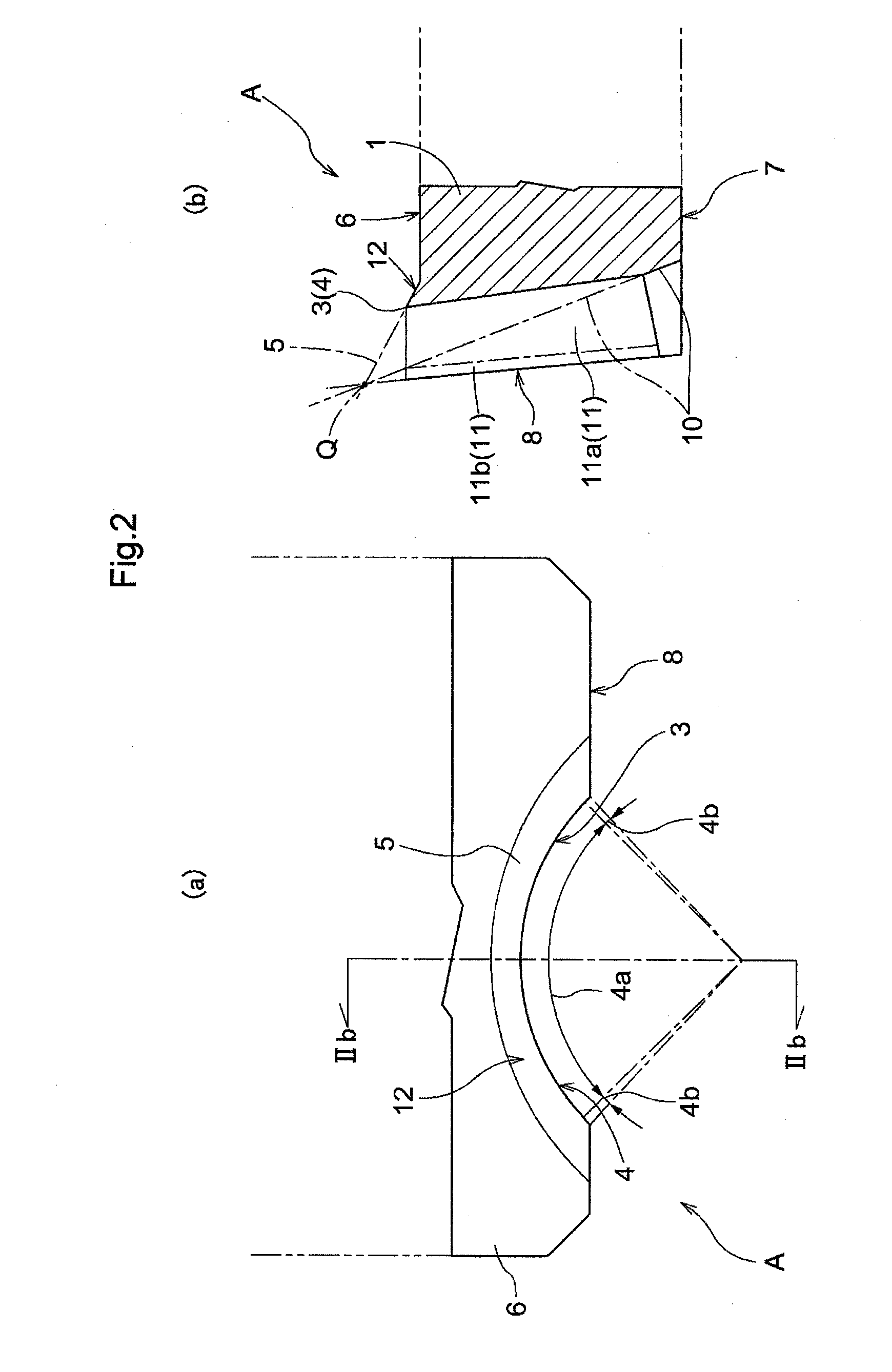
[0038]FIG. 1(a) shows an example where concave cutting edges 4 same in rounding size (curvature of the curved face) are provided at the sides of the base 1. FIG. 1(b) shows an example where cutting edges 4 different in rounding size from one another are formed at the sides of the base 1.

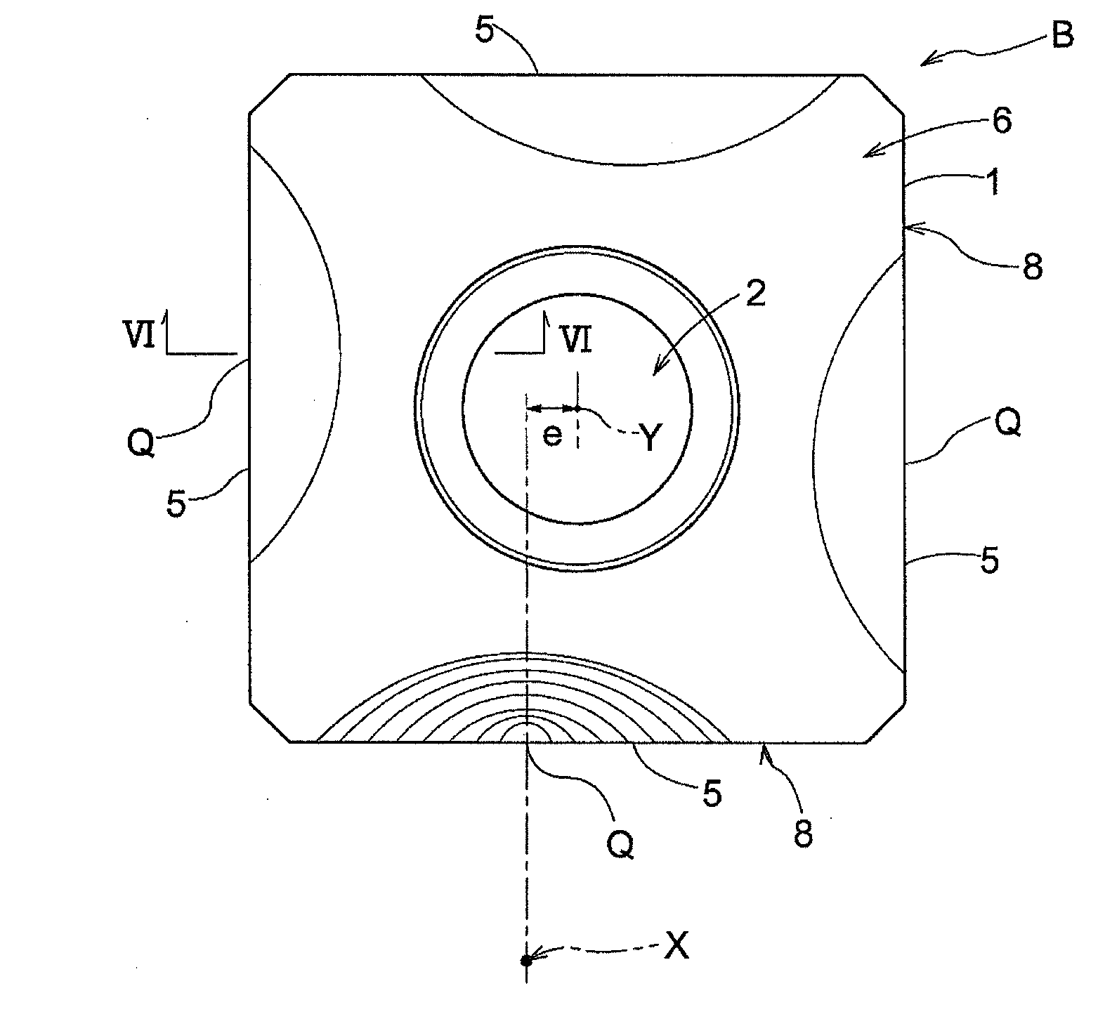
[0039]FIGS. 3 to 6 show a blank B before formation of the cutting edge portions 3. A convex 5 for formation of a rake face is formed in the thickness direc...

second embodiment

[0057]FIGS. 8 to 11 show an insert A of another embodiment.

[0058]In this embodiment, a plurality of convex s 5 for formation of the rake face are provided for each side of the base 1. For example, an outer convex 51 and an inner convex 52 are provided as the convex 5, and a step 16 is provided therebetween. FIGS. 8 and 9 show an example of forming the cutting edge 4 across the outer convex 51, and FIGS. 10 and 11 show an example of forming the cutting edge 4 across the inner convex 52. Two or more convex s may be provided.

[0059]Segmenting the convex in advance into different regions for formation of the cutting edge 4 as described above is convenient because such regions serve as a guide when the user works on the blank to form the cutting edge 4. For example, this not only makes it easy to select the curvature of the cutting edge 4, but also permits formation of the cutting edge 4 at a proper position with the contour lines serving as a guide when a grinding tool is pressed against...

third embodiment

[0060]FIGS. 12 to 14 show an insert A before formation of the cutting edges 4.

[0061]In this embodiment, the step 16 between the outer convex 51 and the inner convex 52 is formed from the top surface 6 of the base 1 itself. Therefore, the difference in the height from the top surface 6 between the outer convex 51 and the inner convex 52 is small.

[0062]The insert A of this embodiment is formed by casting and sintering, for example. The recess between the outer convex 51 and the inner convex 52 may be formed simultaneously with casting, etc., or only the recess may be formed by grinding, etc. after formation of the blank material for the insert A.

Other Embodiments

[0063]In the above embodiments, cutting edges having a single round (part of a circle) shape were described, but the cutting edges are not limited to this shape. For example, concave cutting edges formed by combining a plurality of round shapes may be formed.


PUM

PropertyMeasurementUnit
angleaaaaaaaaaa
shapeaaaaaaaaaa
thicknessaaaaaaaaaa

Abstract

An insert includes a rake angle set corresponding to the hardness of a material to be cut and that can suppress an increase in the material cost even when the strength of a cut edge section is increased. The insert has a polygonal shape and includes a cutting edge portion on at least one side of the polygonal shape. The cutting edge portion includes a rake face having a convex formed on one of opposite surfaces in the thickness direction, a flank face having a concave formed on a surface intersecting with the one surface in the thickness direction and a concave cutting edge that is formed between the rake face and the flank face.

Description

TECHNICAL FIELD[0001]The present invention relates to an insert which has a polygonal shape and includes a cutting edge portion on at least one side of the polygonal shape.BACKGROUND ART[0002]As one type of conventional inserts, there is an insert that is formed into a flat plate shape with its opposite surfaces in the thickness direction being flat and has a rake face formed on one of the flat surfaces (see Patent Document 1, for example)CITATION LISTPatent Document[0003][Patent Document 1] JP 2000-71107ASUMMARY OF INVENTION[0004]In the conventional insert, the rake face is formed on the same level as the flat surface of the insert or formed as a groove thereon. Therefore, if it is intended to obtain a rake angle corresponding to the hardness of a material to be cut, etc., the fixed posture itself of the insert with respect to a rotary cutting tool has to be set as appropriate.[0005]Also, with the rake face formed of the flat surface of the insert, in order to enhance the strength ...

Claims


Application Information

Patent Timeline
Patent Type & Authority Applications(United States)
IPC IPC(8): B23C5/20
CPCB23C5/205B23C5/109B23C5/202B23C2200/085B23C2200/123B23C2200/125B23C2200/203B23C2220/16Y10T407/24B23B29/04B23C5/20B23C5/22
Inventor OGATA, TATSUYA
Owner DAISHOWA SEIKI CO LTD
Why Eureka
Try Eureka