Recirculating fluid filtration system

a filtration system and fluid technology, applied in the direction of filtration separation, multi-stage water/sewage treatment, separation process, etc., can solve the problems of reducing the effectiveness and lifespan of the cross-flow filter, and achieve the effect of optimizing the filtering characteristics of the filter, minimizing the frequency of cleaning operations, and high flow ra

Active Publication Date: 2013-09-26
DEKA PROD LLP
View PDF11 Cites 34 Cited by
  • Summary
  • Abstract
  • Description
  • Claims
  • Application Information

AI Technical Summary

Benefits of technology

[0006]In an embodiment, a two-tiered pumping system may be used, comprising two or more pumps. A feed booster pump supplies fluid from a fluid source and delivers it to the feed fluid recirculation circuit. The pump flow rate can be relatively small—enough to replace the filtered fluid output of the cross-flow filter and any additional fluid discharged from the recirculation circuit. The feed booster pump in combination with a pressure relief device maintains the desired pressure in the recirculation circuit for optimal operation of the filter. In an embodiment, with a filter suitable for use in filtering plasma, the feed booster pump and a flow restriction coil are configured to maintain a recirculation circuit pressure of between approximately 16 kPa and 26 kPa (2.3 psig and 3.8 psig) and an average inlet flow rate of approximately 100 ml/min. Alternatively, when the system is configured with an ultrafilter, the feed booster pump and a flow restriction coil are configured to maintain a recirculation circuit pressure of between approximately 100 kPa and 410 kPa (15 and 60 psig) and an average inlet flow rate of approximately 200 ml/min.
[0007]A feed fluid recirculation pump can be included to circulate fluid through the feed fluid recirculation circuit that comprises a fluid conduit fluidly connecting the retentate outlet of a filter in the circuit with the inlet of the recirculation pump. Preferably, the flow rate generated by the feed fluid recirculation pump is sufficiently high to optimize the filtering characteristics of the filter and minimize the frequency of cleaning operations. A high flow rate may increase the flux of fluid through the cross-flow filter membrane. A high flow rate may also help to pre...

Problems solved by technology

A high flow rate may also help to prevent build-up of mineral scale deposi...

Method used


Image

  • Recirculating fluid filtration system
  • Recirculating fluid filtration system
  • Recirculating fluid filtration system

Examples


Embodiment Construction

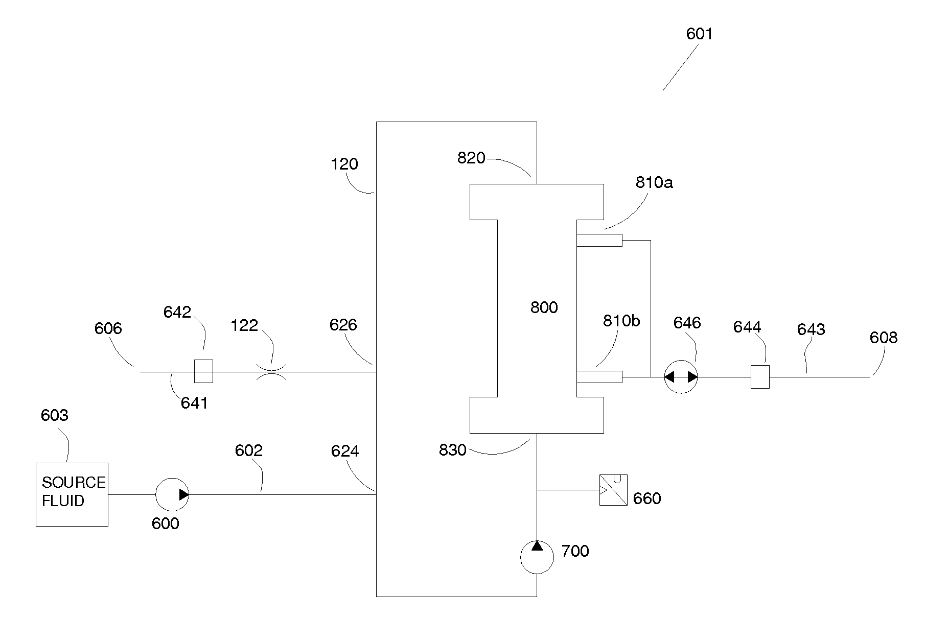
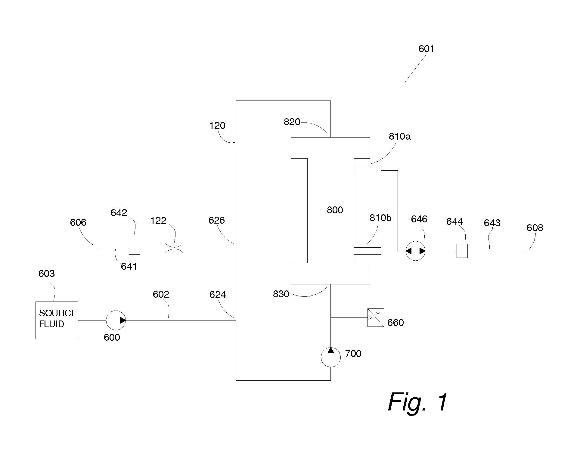
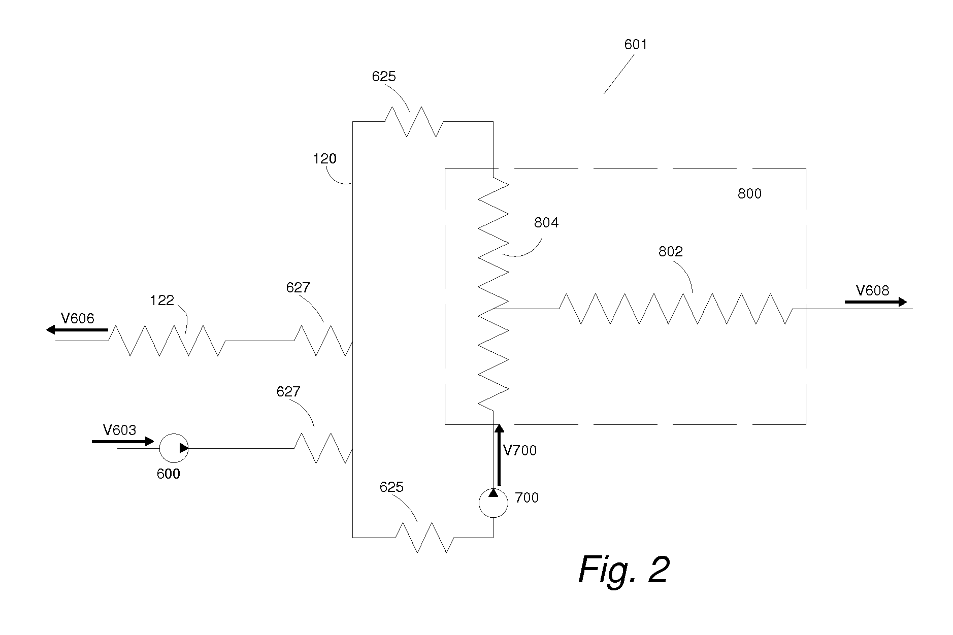
[0013]The term “downstream” as used herein indicates a position in the flow path, with respect to a current position or point of discussion, which will be reached in time with the normal movement of fluid through the system. Arrowheads along the flow path in the figures indicate the normal direction of fluid flow. The term “upstream” may be used to indicate a position in a direction that opposes normal fluid flow, i.e., opposes the direction of the arrowheads.

[0014]FIG. 1 shows basic elements of cross-flow filter system 601 that comprises a cross-flow filter 800, a return loop 120, a supply / booster pump 600 and recirculation pump 700. The cross-flow filter system 601 filters the feed fluid from the source 603, delivers the filtered fluid or permeate to port 608, while delivering concentrated feed or retentate to port 606. In other embodiments the cross-flow filter system 601 may be part of a larger system that may have preferred operating parameters including but not limited to supp...


PUM

PropertyMeasurementUnit
Fractionaaaaaaaaaa
Flow rateaaaaaaaaaa
Volumeaaaaaaaaaa

Abstract

A fluid filtration system comprising a cross-flow filter is arranged to permit a first pump to recirculate part of the retentate of the filter to the inlet of the cross-flow filter and a second pump to return part of the permeate to the inlet of the cross-flow filter. A third pump is configured supply source fluid to the inlet of the filter. The flow path between the second pump and the cross-flow filter inlet may include an adsorption filter that may selectively remove contaminants, toxins, or pathogens in the permeate. A controller may control the first, second and third pumps to provide predetermined flow ratios among the fluid flow paths of the system in order to achieve a desired filtration level. This system may be applicable to the removal of harmful substances from blood, by first separating the plasma from the blood and then removing harmful substances from the plasma.

Description

CROSS-REFERENCE TO RELATED APPLICATIONS[0001]This application claims the benefit of U.S. Provisional Patent Application Ser. No. 61 / 535,135, filed Sep. 15, 2011, and entitled Optimized Flow Loop for Fluid Filtration (Attorney Docket No. J01), which is hereby incorporated by reference herein in its entirety.TECHNICAL FIELD[0002]The present invention relates to fluid filtration systems and methods.BACKGROUND[0003]In chemical engineering, biochemical engineering and protein purification, cross-flow filtration (also known as tangential flow filtration) is a type of filtration where the majority of the feed flow travels tangentially across the surface of the filter, rather than through the filter. The permeate passes through the filter membrane or filter media, while the retentate exits the filter body carrying the particles too large to pass through the filter element. A range of different types of membranes are available that can be characterized by the size of the particles and solute...

Claims


Application Information

Patent Timeline
IPC IPC(8): A61M1/16
CPCA61M1/16A61M1/3472A61M1/3486A61M1/3482A61M1/3624A61M1/3601B01D37/04B01D24/48A61M1/3679A61M1/3633A61M2202/0413A61M2202/0415A61M2202/049A61M2202/203A61M2202/206B01D37/046
Inventor KENLEY, RODNEY S.LAROCQUE, RYAN K.SCHNELLINGER, ANDREW A.
Owner DEKA PROD LLP
Why Eureka
Try Eureka