
Alternate reduction ratios and threshold mechanisms for framebuffer compression

a framebuffer and compression technology, applied in the field of graphic processing, can solve the problems of affecting the ability to process graphics data, affecting the processing of color information and other information, e.g. stencil and depth data, occupying a large amount of memory, and affecting the processing of graphics data, so as to reduce any loss, maximize compression, and improve throughput or computational performance

Active Publication Date: 2013-09-26
NVIDIA CORP
View PDF4 Cites 16 Cited by
  • Summary
  • Abstract
  • Description
  • Claims
  • Application Information

AI Technical Summary

Benefits of technology

The patent is about a need for a better way to compress the framebuffer of a video or image. The new technology should improve throughput and computational performance by using a reduction ratio that is not tied to the number of samples being used. The new compression scheme should also be more robust, with a mechanism to perform threshold comparisons to maximize compression and reduce loss to the lowest possible error for each sample.

Problems solved by technology

In particular, color information and other information, e.g., stencil and depth data, that is typically stored in the framebuffer takes up a large amount of memory.
In addition, the time it takes to transfer color data from memory to a graphics processor can negatively affect the ability to process graphics data.
However, the demand on system resources increases in proportion to the number of samples.
Three-dimensional data processing is very data intensive.
However, because they tie the number of samples in a group being reduced to the reduction ratio, conventional systems may be limited in the advantages they offer.
Conventional systems were unable to compress color data or other types of data, e.g., depth and stencil data for a tile without introducing visual artifacts.

Method used


Image

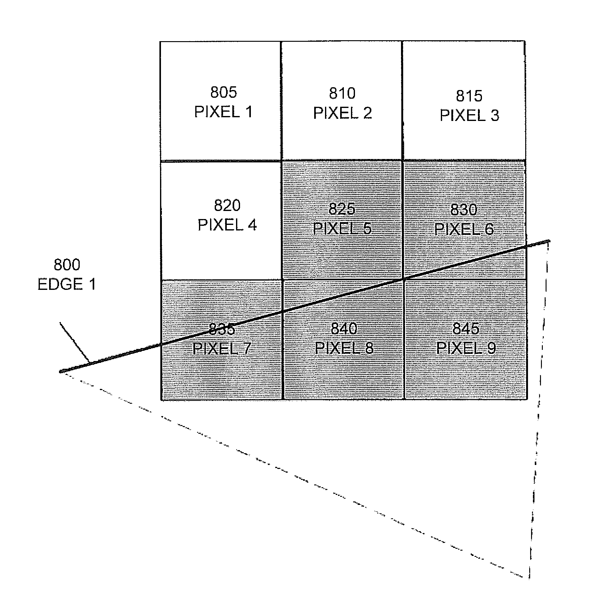
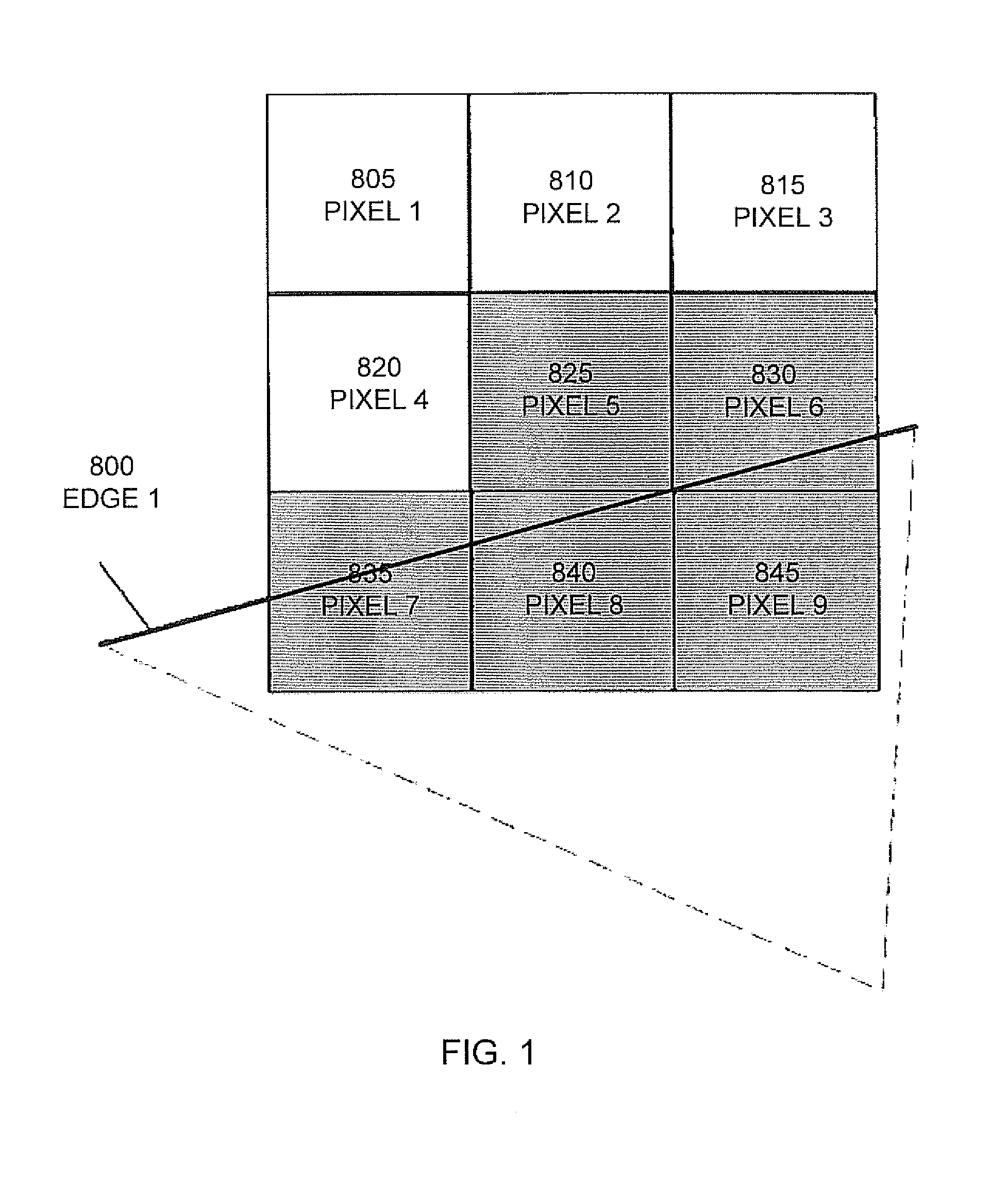
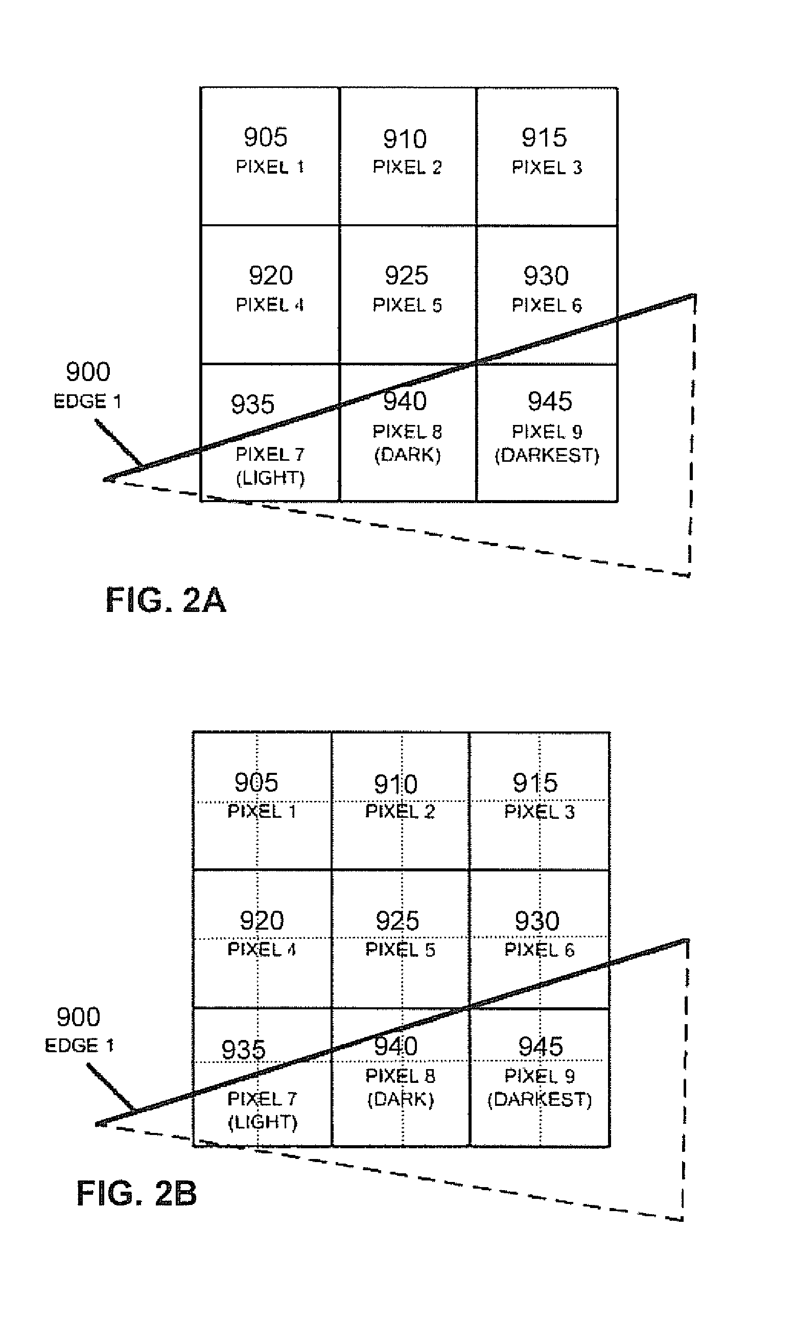
  • Alternate reduction ratios and threshold mechanisms for framebuffer compression
  • Alternate reduction ratios and threshold mechanisms for framebuffer compression
  • Alternate reduction ratios and threshold mechanisms for framebuffer compression

Examples


Embodiment Construction

[0042]Reference will now be made in detail to the various embodiments of the present disclosure, examples of which are illustrated in the accompanying drawings. While described in conjunction with these embodiments, it will be understood that they are not intended to limit the disclosure to these embodiments. On the contrary, the disclosure is intended to cover alternatives, modifications and equivalents, which may be included within the spirit and scope of the disclosure as defined by the appended claims. Furthermore, in the following detailed description of the present disclosure, numerous specific details are set forth in order to provide a thorough understanding of the present disclosure. However, it will be understood that the present disclosure may be practiced without these specific details. In other instances, well-known methods, procedures, components, and circuits have not been described in detail so as not to unnecessarily obscure aspects of the present disclosure.

[0043]S...


PUM


Abstract

A method for compressing framebuffer data is presented. The method includes determining a reduction ratio for framebuffer data in a tile including multiple samples. The reduction ratio determined is independent of the sampling mode, where the sampling mode is the number of samples within each pixel in the tile. The method further includes comparing a first portion of the framebuffer data for each of the multiple samples to determine an equality comparison result and also comparing a second portion of the framebuffer data for each one of the multiple samples to compute per-channel differences for each one of the multiple samples and testing the per-channel differences against a threshold value to determine a threshold comparison result. Finally, the method comprises compressing the framebuffer data for the tile based on the reduction ratio, the equality comparison result and the threshold comparison result to produce output framebuffer data for the tile.

Description

CROSS-REFERENCE TO RELATED APPLICATIONS[0001]This application is a continuation-in-part of co-pending U.S. patent application Ser. No. 12 / 651,357 “THRESHOLD-BASED LOSSY REDUCTION COLOR COMPRESSION” Attorney Docket NVDA / SC-08-0504-US1, David K. McAllister, filed Dec. 31, 2009, which is hereby incorporated by reference in its entirety.FIELD OF THE INVENTION[0002]Embodiments according to the present invention generally relate to graphics processing and more specifically to compression of color data.BACKGROUND OF THE INVENTION[0003]Three dimensional graphics processing applications require the storage and processing of large amounts of data. In particular, color information and other information, e.g., stencil and depth data, that is typically stored in the framebuffer takes up a large amount of memory. In addition, the time it takes to transfer color data from memory to a graphics processor can negatively affect the ability to process graphics data. There is a need to reduce the amount...

Claims


Application Information

Patent Timeline
Patent Type & Authority Applications(United States)
IPC IPC(8): G06T5/00
CPCG06T5/002G06T9/00G09G5/363G09G5/39H04N19/426G09G2340/10G09G2360/06G09G2360/121G09G2360/122G09G2340/02G06T5/70
Inventor DUNAISKY, JONATHANMCALLISTER, DAVID KIRKMOLNAR, STEVEN E.KULSHRESTHA, NARAYANBASTOS, RUIDETMER, JOSEPHMCKNIGHT, WILLIAM CRAIG
Owner NVIDIA CORP
Learn More