Piezoelectric thin film element and method of manufacturing the same, droplet discharge head and inkjet recording device using the piezoelectric thin film element

a technology of piezoelectric thin film and droplet discharge head, which is applied in the direction of vacuum evaporation coating, inking apparatus, generator/motor, etc., can solve the problems of pb likely to diffuse to the base electrode, difficulty in forming conductive oxide srruo, and oxygen deficiency in piezoelectric thin film (piezoelectric film, piezoelectric material) may increase, so as to improve the crystalline state of conductive oxid

Active Publication Date: 2013-09-26
RICOH KK
View PDF5 Cites 30 Cited by
  • Summary
  • Abstract
  • Description
  • Claims
  • Application Information

AI Technical Summary

Benefits of technology

[0023]Thus, the present disclosure provides a piezoelectric thin film element, a method of manufacturing the piezoelectric thin film element, and a droplet discharge head and an inkjet recording device which use the piezoelectric thin film element. Specifically, an electromechnical conversion element having a piezoelectric thin film (piezoelectric ma...

Problems solved by technology

However, columnar crystal grains grow due to a high orientation, and thus there is a problem in that an element such as Pb is likely to diffuse to the base electrode along grain boundaries.
In addition, in the conventional technology, a possibility has been pointed out that oxygen deficiency in the piezoelectric thin film (piezoelectric film, piezoelectric material) may increase over time during the operation of the piezoelectric thin film (piezoelectric film, piezoelectric material).
When holes are formed in the platinum film in this manner, the continuity of a conductive oxide crystal is blocked due to the holes, and thus it is difficult to form the conductive oxide SrRuO3 film having an average particle diameter greater than that of the p...

Method used


Image

  • Piezoelectric thin film element and method of manufacturing the same, droplet discharge head and inkjet recording device using the piezoelectric thin film element
  • Piezoelectric thin film element and method of manufacturing the same, droplet discharge head and inkjet recording device using the piezoelectric thin film element
  • Piezoelectric thin film element and method of manufacturing the same, droplet discharge head and inkjet recording device using the piezoelectric thin film element

Examples


embodiment 1

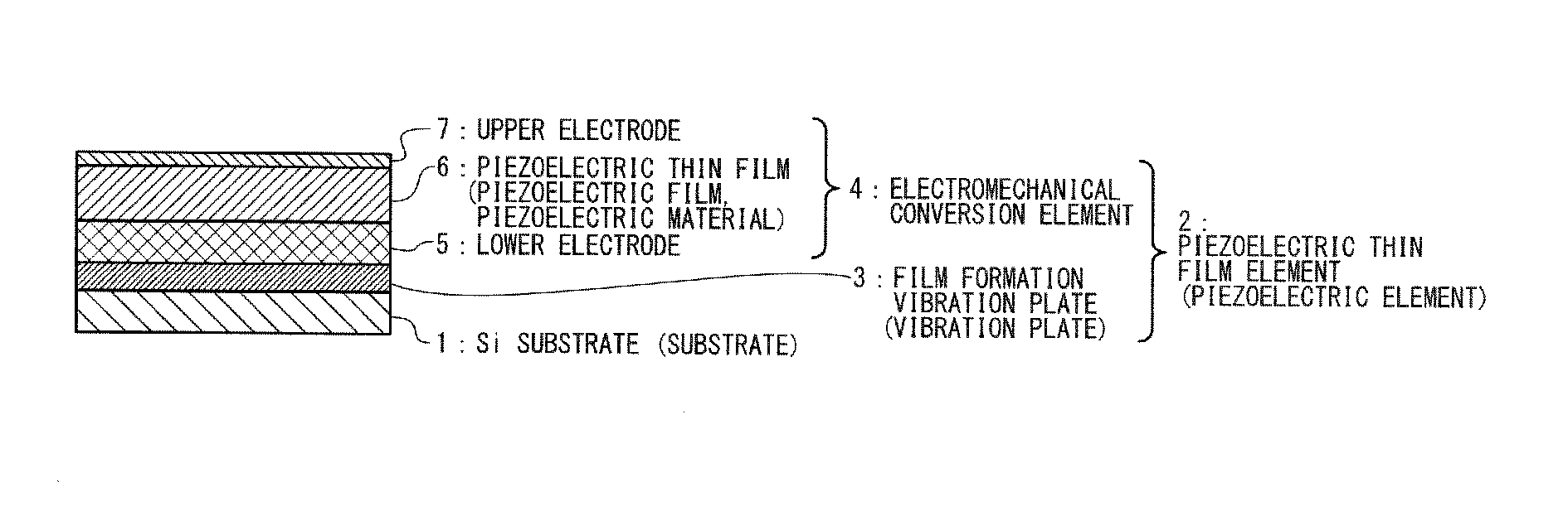
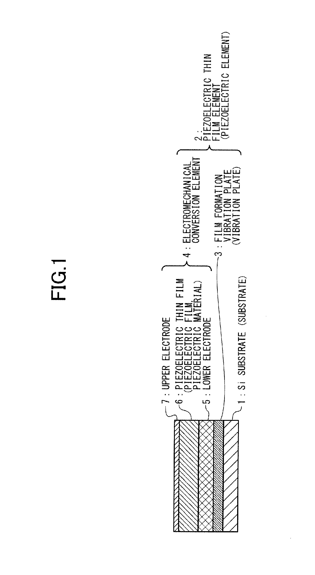
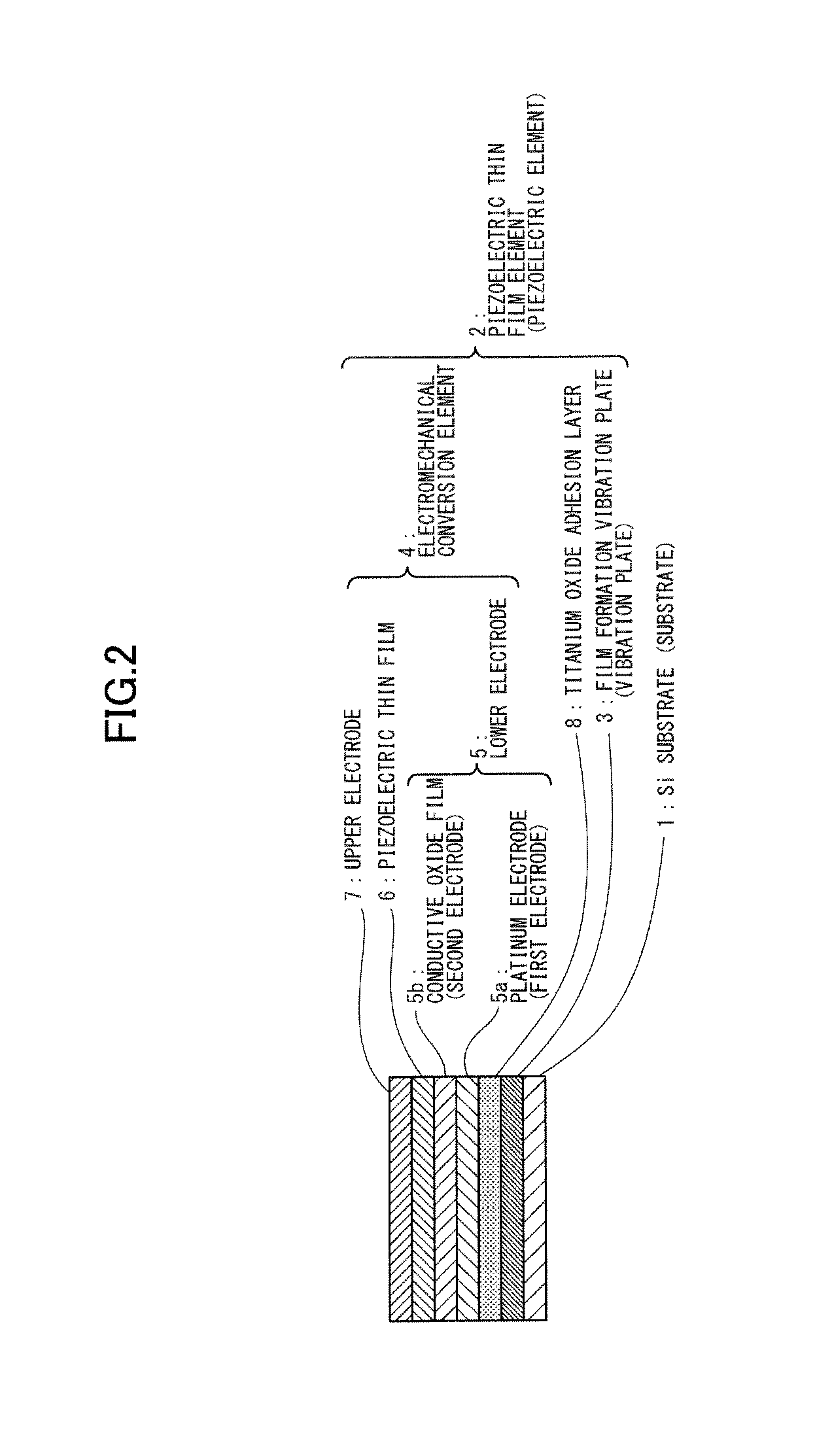
[0041]FIG. 1 illustrates a schematic configuration of the piezoelectric thin film element (piezoelectric element) according to the present disclosure; and FIG. 2 illustrates a more detailed configuration of the piezoelectric thin film element illustrated in FIG. 1.

[0042]The piezoelectric thin film element (piezoelectric actuator) illustrated in FIG. 1 includes a substrate 1, and a piezoelectric thin film element (piezoelectric element) 2 provided on the substrate 1. The piezoelectric thin film element (piezoelectric element) 2 includes a film formation vibration plate 3 provided (stacked) on the substrate 1, and an electromechanical conversion element provided (stacked) on the film formation vibration plate 3. The electromechanical conversion element has a lower electrode 5 provided (stacked) on the film formation vibration plate 3, a piezoelectric thin film (hereinafter referred to as a piezoelectric material or a piezoelectric film as needed) 6, and an upper electrode 7 provided (...

embodiment 2

[0051]FIG. 3 illustrates a schematic configuration of the inkjet recording head (droplet ejection head) Hd having the piezoelectric actuator in FIG. 1.

[0052]The inkjet recording head Hd in FIG. 3 uses the piezoelectric actuator which has the configuration illustrated in FIGS. 1 and 2. In the inkjet recording head Hd in FIG. 3, the substrate 1 is provided with a pressure cavity (compression cavity) 1a which is open at upper and lower ends. A nozzle plate 9 is then installed at the lower end of the substrate 1 so as to close the lower open end of the pressure cavity 1a, and a nozzle 9a which communicates with the pressure cavity 1a to eject the ink in the pressure cavity 1a is provided in the nozzle plate 9. In addition, the upper open end of the pressure cavity 1a is closed by the film formation vibration plate 3.

[0053]It is to be noted that more specific materials and manufacturing process for the substrate 1 and the piezoelectric thin film element 2 in FIGS. 1 and 2 are the same as...

embodiment 3

[0084]FIG. 6 is a cross-sectional view illustrating a color inkjet recording head CHd in Embodiment 3, which is formed by arranging side by side multiple inkjet recording heads (droplet ejection head) Hd in FIG. 3. In FIG. 6, the film formation vibration plate 3, the nozzle plate 9, and the lower electrode 5 can be commonly used as illustrated. In FIG. 6, yellow (Y), magenta (M), cyan (C), and black (Bk) inkjet record heads are provided.


PUM

PropertyMeasurementUnit
Temperatureaaaaaaaaaa
Thicknessaaaaaaaaaa
Lattice constantaaaaaaaaaa

Abstract

A piezoelectric thin film element includes a vibration plate, a lower electrode provided on the vibration plate and made of a conductive oxide, a piezoelectric thin film provided on the lower electrode and made of a polycrystalline substance, and an upper electrode provided on the piezoelectric thin film, wherein the lower electrode includes a titanium oxide film formed on the vibration plate, a platinum film formed on the titanium oxide film, and a conductive oxide film formed on the platinum film and, the platinum film and the conductive oxide film being a solid film with no holes.

Description

PRIORITY CLAIM[0001]The present application is based on and claims priority from Japanese Patent Application No. 2012-066087, filed on Mar. 22, 2012, the disclosure of which is hereby incorporated by reference in its entirety.BACKGROUND[0002]1. Field of the Invention[0003]The present disclosure relates to a piezoelectric thin film element for use in an inkjet recording head or the like, and a method of manufacturing the piezoelectric thin film element, and to a droplet discharge head and an inkjet recording device using the piezoelectric thin film element.[0004]2. Description of the Related Art[0005]Some of conventional image recording devices and imaging devices such as a printer, a facsimile, and a copy machine use an inkjet recording device equipped with an inkjet recording head as a liquid discharge head (liquid ejection head). Two types of inkjet recording heads (ink ejection heads) are practically used: one uses a longitudinal vibration mode piezoelectric actuator which extend...

Claims


Application Information

Patent Timeline
IPC IPC(8): H01L41/047B41J2/045H01L41/314H01L41/09
CPCB41J2/1646B41J2/045B41J2/14233B41J2202/03B41J2/1628B41J2/161B41J2/1642B41J2/1629H01L41/0478B41J2/1645H01L41/314B41J2/1631H01L41/29B41J2002/14241H01L41/318H01L41/0973H01L41/0477H10N30/878H10N30/877H10N30/2047H10N30/06H10N30/078H10N30/074
Inventor ISHIMORI, MASAHIROSHINKAI, MASARUMIZUKAMI, SATOSHI
Owner RICOH KK
Why Eureka
Try Eureka