Fast response thermopile power sensor

a technology of thermopile power and sensor, which is applied in the field of laser power measurement, can solve the problems of limited power handling capacity the typical response time of such a sensor is no faster than 1 sec, so as to shorten the distance the heat has to travel and achieve the effect of fast response, shortening the response time and shortening the distan

Active Publication Date: 2013-09-26
OPHIR OPTRONICS SOLUTIONS LTD
View PDF6 Cites 12 Cited by
  • Summary
  • Abstract
  • Description
  • Claims
  • Application Information

AI Technical Summary

Benefits of technology

[0006]The power measurement discs described in this disclosure achieve a faster response by substantially shortening the distance the heat has to travel from the point of impingement on the disc, to the point of heat sinking of the absorbed power. There is described a laser power sensor, similar in dimensions to the above-described prior art radial thermopile type, but arranged so that the heat flow path is much shorter, thus providing response times faster by an order of magnitude or more. This short heat flow path is provided by allowing the heat generated by the power incident on an absorber surface of the disc to flow axially across a thin heat insulating layer between two thermopiles, with the operative temperature measurement junctions being in the central region of the device, situated in the region of the heat flow. The pair of thermopiles operate in this configuration as temperature measurement devices, with their hot junctions in the region where the heat flow passes. Since the temperature drop across the heat insulating layer is proportional to the heat flow across it, the difference in temperature measured between the central regions of the two thermopiles provides a measure of the incident power. The cold outer junctions of both of the thermopiles are assumed to be essentially at the same temperature, since they are not in the path of the heat flow, such that the difference in outputs of the two thermopiles is proportional to the difference in temperatures between the hot junctions, which itself is proportional to the axial heat flow across the disc. This arrangement can be implemented in practice by sandwiching the heat insulating layer between a pair of thermopiles having hot junctions in the central region and cold junctions in the outer region. The heat flowing axially down the stack is absorbed by a cooled heat sink covering the whole of the area of the thermopiles.
[0007]As a further implementation of the axial flow power sensors of this disclosure, a single layer thermopile can be used instead of the double layers described hereinabove. The thermopiles are then constructed in the form of a continuous matrix of adjacent thermocouple junctions over the heat flow region of the sensor disc, with the thermal insulating layer, which generates the temperature drop, being thicker at alternate junctions. The junctions on the thicker regions of the insulator thus become the hot junctions, and those on the thinner regions of the insulating layer become the cold junctions. The heat drop across the insulating layer is thus generated on adjacent rather than collinear hot and cold junctions. Such a structure may provide a more uniform heat absorption configuration over a larger area, and may be simpler to construct because of the smaller number of component parts, and the simpler planar deposition method of construction.

Problems solved by technology

The disadvantage is that even with time response accelerating circuits and software, the response time of such a sensor is typically no faster than 1 sec. for reaching 95% of the final reading.
Typically, for a disc designed to measure powers of the order of a few tens of Watts, this distance is of the order of 10 mm In addition, due to the relatively long heat path, the power handling capacity of such a sensor may be limited.

Method used


Image

  • Fast response thermopile power sensor
  • Fast response thermopile power sensor
  • Fast response thermopile power sensor

Examples


Embodiment Construction

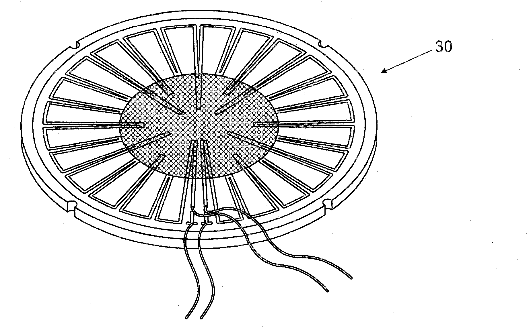
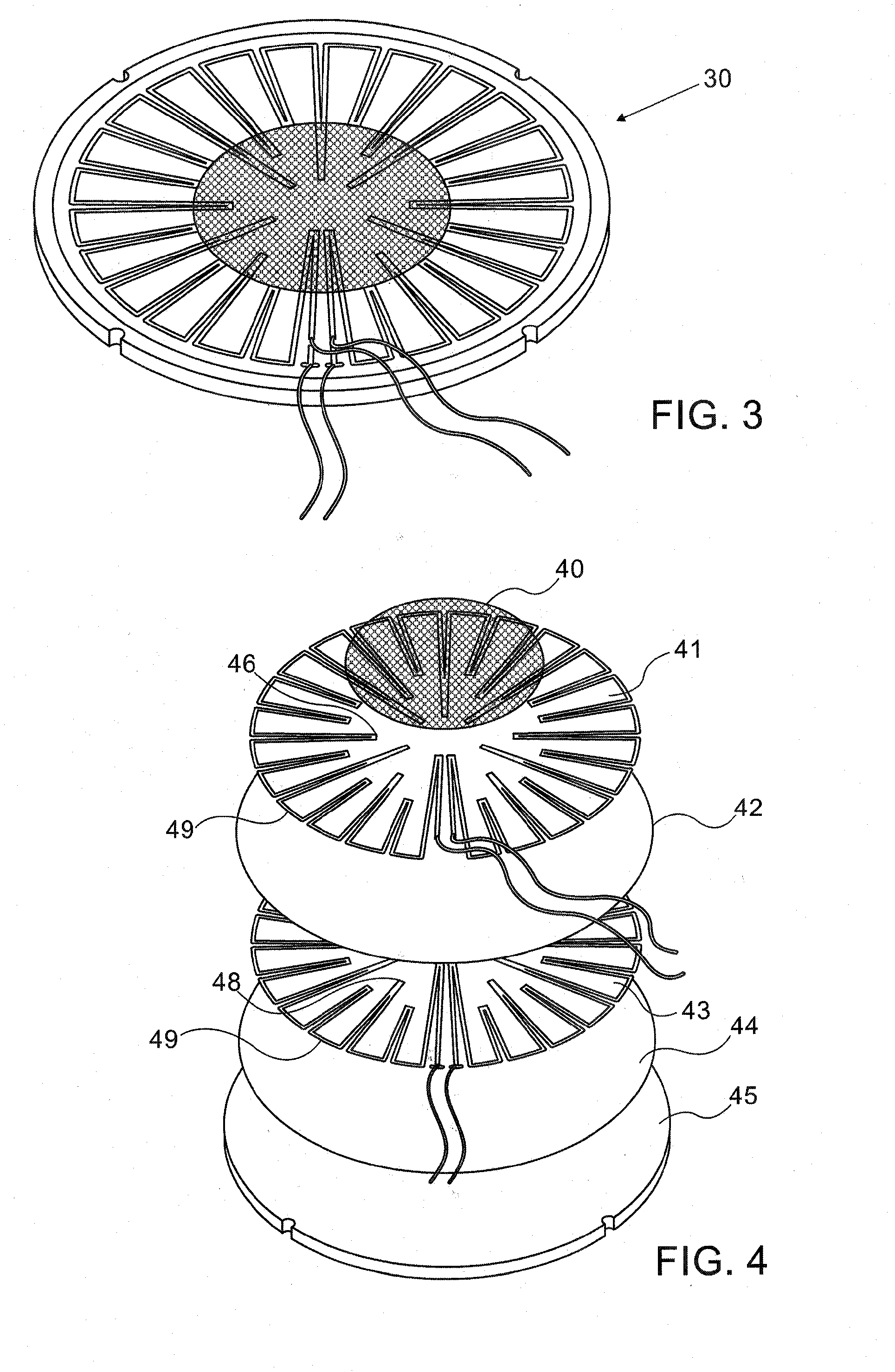
[0055]Reference is now made to FIGS. 3 and 4 which illustrate schematically an exemplary power measurement disc of a first type described in this disclosure. FIG. 3 shows an assembled disc 30 while FIG. 4 is an exploded view, showing the component parts. The device consists of a layered stacked structure, each of whose layers are in good thermal contact with their immediately neighboring layers, and comprising, in order from the power absorbing surface:

[0056](i) an absorbing layer 40 capable of withstanding the incident beam power density;

[0057](ii) a first radial thermopile 41;

[0058](iii) a first insulating layer 42;

[0059](iv) a second radial thermopile 43;

[0060](v) a second insulating layer 44; and

[0061](vi) a conductive heat sinking layer 45.

The radial thermopiles differ from the thermopiles used in the prior art discs as described above, in that the hot junctions 46 extend towards the center of the disc assembly, and are spread over the entire area in the region opposite the sur...


PUM

PropertyMeasurementUnit
response timeaaaaaaaaaa
distanceaaaaaaaaaa
response timeaaaaaaaaaa

Abstract

A power measuring sensor for an optical beam which utilizes the temperature difference across a thin layer of heat insulating material, generated by the axial flow of the absorbed beam, from an absorber layer on which the beam impinges, to a cooled heat sink which dissipates the heat after passage through the sensor. The axial heat flow is measured by means of a continuous matrix of adjacent thermocouple junctions over the heat flow region of the sensor disc, with the thermal insulating layer, which generates the temperature drop, having thicker and thinner regions at alternate junctions. The junctions on the thicker regions of the insulator thus become the hot junctions, and those on the thinner regions of the insulating layer become the cold junctions, and the sum of the voltages generated by the thermocouples is proportional to the flow of heat, and thus to the incident optical power.

Description

FIELD OF THE INVENTION[0001]The present invention relates to the field of laser power measurements, and especially to the ability to monitor rapid changes in laser power.BACKGROUND OF THE INVENTION[0002]A common form of thermal sensor for laser power measurement is based on a thermopile, disposed on the outer periphery of a thermally conductive disc, so that it measures the radial temperature gradient of the disc at the outer periphery. FIG. 1 illustrates such a prior art disc, with the laser beam 15 impinging in the central section of the disc and the disc cooled around its periphery 12. The heat flows radially, causing a temperature drop between the hot and cold thermocouple junctions thus producing a voltage proportional to power input. The thermopile 10 is located towards the outer edge of the disc, and the cooling region is at the periphery 12, outside of the thermopile. FIG. 2 shows such a disc 20 mounted in a laser power meter head, with its outer edge 22 in good thermal cont...

Claims


Application Information

Patent Timeline
Patent Type & Authority Applications(United States)
IPC IPC(8): G01K11/00
CPCG01K11/00G01K17/003
Inventor GREENFIELD, EPHRAIMBENDER, ELIYAHUELSTEIN, SHIMON
Owner OPHIR OPTRONICS SOLUTIONS LTD
Why Eureka
Try Eureka