
Vehicular hybrid drive system

a hybrid drive and vehicle technology, applied in the direction of automatic control systems, process and machine control, instruments, etc., can solve the problems of deterioration of fuel economy, risk of insufficient cooling of the above-described first electric motor, etc., to improve the fuel economy of the vehicle, reduce the amount of working oil, and reduce the effect of dragging power loss

Active Publication Date: 2013-09-26
TOYOTA JIDOSHA KK
View PDF0 Cites 24 Cited by
  • Summary
  • Abstract
  • Description
  • Claims
  • Application Information

AI Technical Summary

Benefits of technology

The present invention provides a vehicular hybrid drive system that can improve fuel economy and reduce dragging power loss by cooling the motor during different driving modes. The system uses less amount of working oil for cooling during the second driving mode which has lower needs for cooling. This is achieved by controlling the amount of working oil supplied to the motor based on its temperature, vehicle speed, and required drive force. The system also includes an electric oil pump or a hydraulic circuit to control the amount of working oil supplied to the motor. Additionally, the system includes two electric motors, one designed for cooling and the other designed for assisting the vehicle's drive force. The second electric motor is designed to generate the larger drive force, reducing the amount of working oil needed to cool the first motor. These technical effects improve fuel economy and reduce power loss in a hybrid vehicle.

Problems solved by technology

As a result, the amount of the working oil used for cooling the electric motors is excessively large in the above-described second drive mode, leading to deterioration of the fuel economy, and a risk of insufficient cooling of the above-described first electric motor in the above-described first drive mode.

Method used


Image

  • Vehicular hybrid drive system
  • Vehicular hybrid drive system
  • Vehicular hybrid drive system

Examples


first embodiment

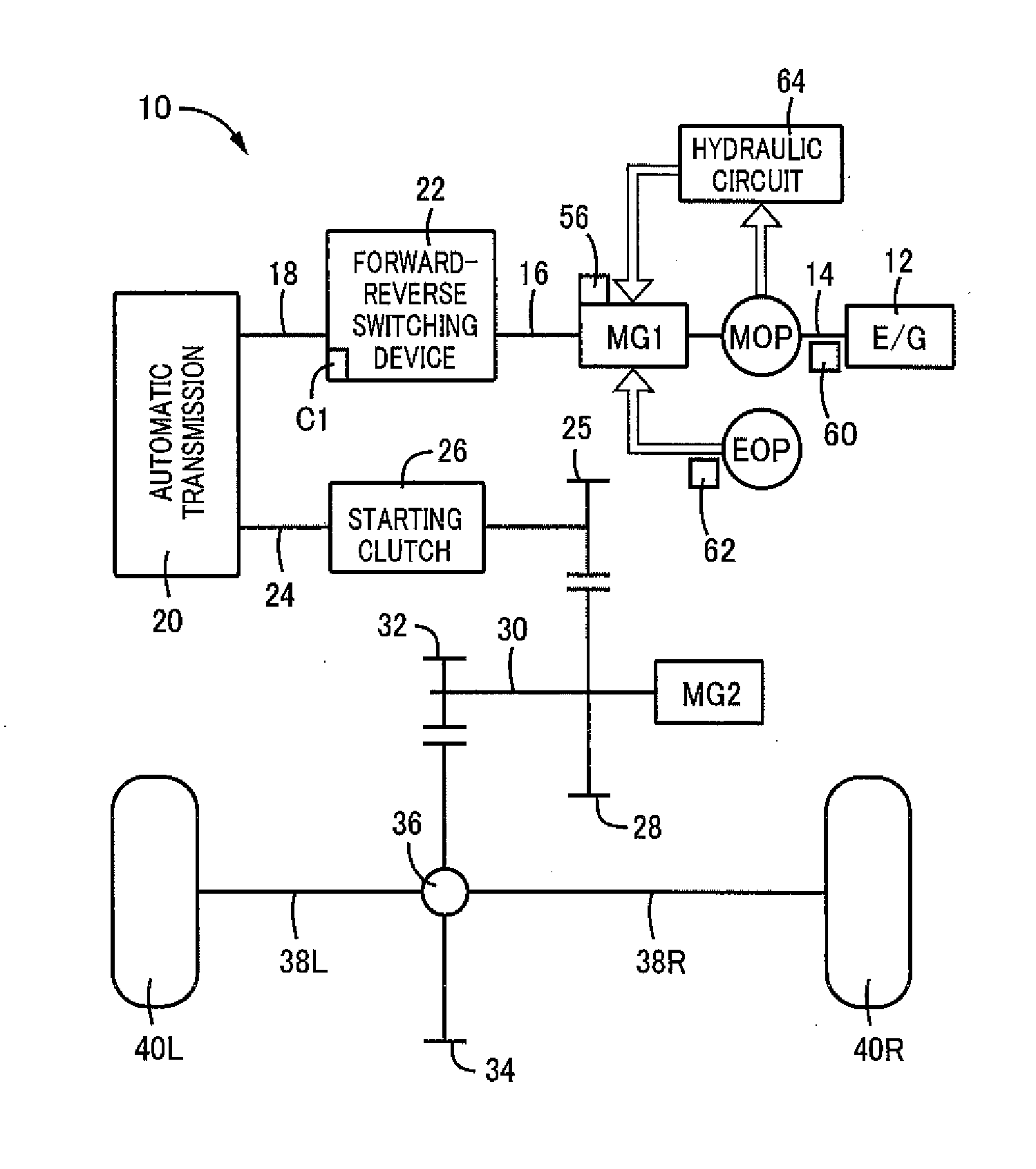
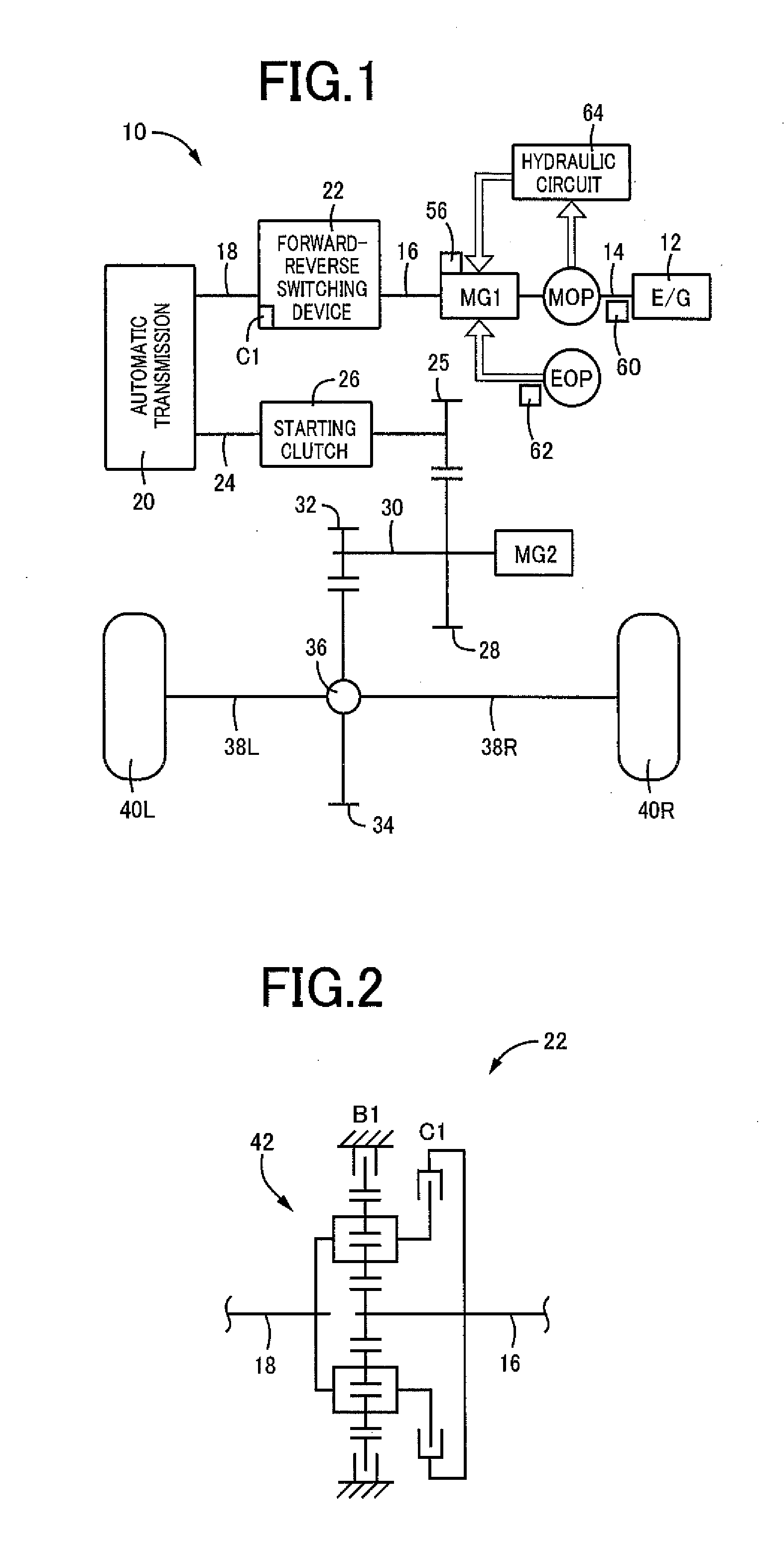
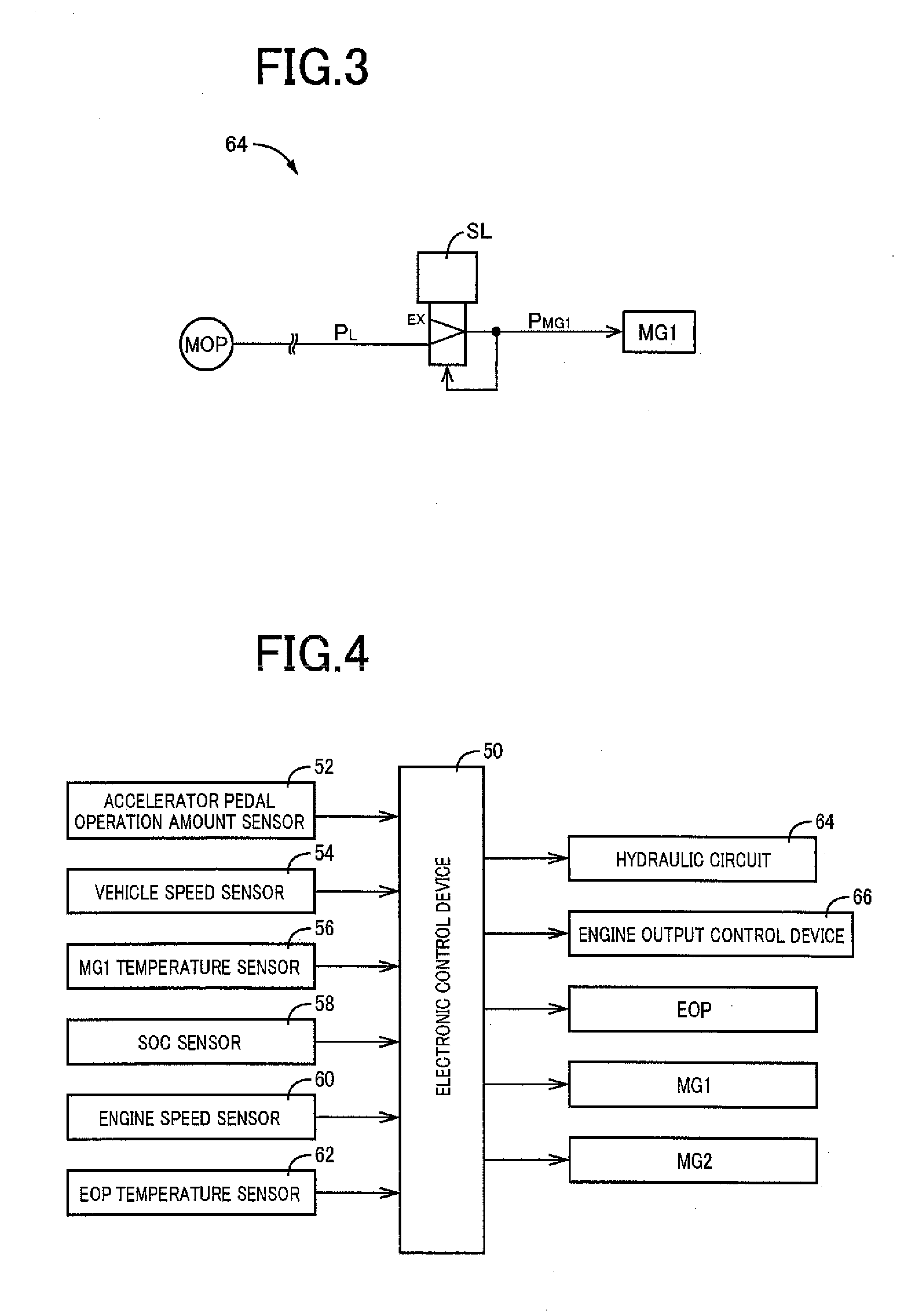
[0026]FIG. 1 is the schematic view shown the arrangement of a vehicular hybrid drive system 10 to which the present invention is suitably applicable. As shown in FIG. 1, the hybrid vehicle according to the present invention is provided with: an engine 12; a first motor / generator MG1 connected to a crankshaft 14 of the engine 12; a forward-reverse switching device 22 connected to the first motor / generator MG1 through an intermediate shaft 16 and to an automatic transmission 20 through an input shaft 18; a starting clutch 26 interposed between an output shaft 24 of the automatic transmission 20 and a first gear 25 and configured to selectively place a power transmitting path therebetween in a power transmitting state and a power cut-off state; a counter shaft 30 on which a second gear 28 meshing with the first gear 25 is mounted; a second motor / generator MG2 connected to the counter shaft 30; a third gear 32 mounted on the counter shaft 30; a differential gear device 36 provided with ...

second embodiment

[0062]FIG. 10 is the schematic view showing an arrangement of another vehicular hybrid drive system to which the present invention is suitably applicable. In this hybrid drive system 100 shown in FIG. 10, the above-described engine 12 is subjected to a cranking action by a starter motor 102 connected to the crankshaft 14 through a belt, for example. The hybrid drive system 100 is provided with a step-variable automatic transmission 104 of a planetary gear type, for instance, which has a plurality of speed positions and a neutral position which are selectively established by engaging and releasing actions of a plurality of clutches and brakes. Between an input shaft 106 of the automatic transmission 104 and the crankshaft 14, there is interposed a starting clutch 108 configured to selectively place a power transmitting path therebetween in a power transmitting state and a power cut-off state. The above-indicated starter motor 102 is a motor / generator which also has a function of an e...

third embodiment

[0064]FIG. 11 are the views for explaining a further vehicular hybrid drive system to which the present invention is suitably applicable, FIG. 11(a) being the schematic view showing an arrangement of the hybrid drive system, while FIG. 11(b) being the view for explaining a plurality of drive modes to be selectively established in the hybrid drive system. In this hybrid drive system 150 shown in FIG. 11, the above-described engine 12, a first clutch 152, the first motor / generator MG1, a second clutch 154 and the second motor / generator MG2 are disposed in series coaxially with each other, and an output gear 156 interposed between the second clutch 154 and the second motor / generator MG2 is held in meshing engagement with the above-described fourth gear 34. Like the drive system of the vehicular hybrid drive system 10 described above with respect to the preceding embodiment, the present hybrid drive system 150 is configured to selectively establish one of the “EV” drive mode, the “serie...


PUM


Abstract

A hybrid drive system configured to selectively establish one of a first drive mode in which a first motor / generator MG1 is operated with a drive force of an engine, to generate an electric energy and in which a vehicle drive force is generated primarily by a second motor / generator MG2, and a second drive mode in which the vehicle drive force is generated by the engine, and at least one of the first motor / generator MG1 and second motor / generator MG2 is operated to generate an assisting vehicle drive force, as needed, and further configured such that an amount of a working oil to be supplied to the first motor / generator MG1 is larger in the first drive mode than in the second drive mode, permitting sufficient cooling of the electric motor depending upon a selected one of the vehicle drive modes.

Description

TECHNICAL FIELD[0001]The present invention relates to a vehicular hybrid drive system, and more particularly to an improvement of the hybrid drive system, which permits sufficient cooling of an electric motor depending upon a selected one of vehicle drive modes.BACKGROUND ART[0002]There is known a vehicular hybrid drive system provided with an engine, a first electric motor connected to the engine, and a second electric motor connected to drive wheels. There has been proposed a technique to suitably cooling an electric motor depending upon a selected drive mode of such a vehicular hybrid drive system. Patent Document 1 discloses an example of a cooling device for practicing the technique. This cooling device is configured to control a delivery amount of an oil pump such that an amount of a working oil to be supplied to the electric motor is larger in a drive mode of the hybrid drive system in which a vehicle drive force generated according to a selected output characteristic at an o...

Claims


Application Information

Patent Timeline
Patent Type & Authority Applications(United States)
IPC IPC(8): B60W20/00B60W10/30B60W10/08B60L50/16
CPCB60W10/08B60W10/30B60W20/20B60W2600/00Y02T10/6239B60K6/445B60W20/00B60W30/1843B60W2510/087Y10S903/93Y02T10/62B60W2556/00
Inventor NISHIMINE, AKIKOHAYASHI, KOJIKANAYAMA, TAKESHIHORI, TETSUOMARUYAMA, TOMOYUKIMIYAGAWA, TAKESHIII, RYOKIFURUKAWA, TOMOAKIYAMAMURA, NORIHIROSATO, AKIHIRO
Owner TOYOTA JIDOSHA KK
Learn More