Memory controller and memory storage device and data writing method

Active Publication Date: 2013-09-26
PHISON ELECTRONICS
View PDF2 Cites 6 Cited by
  • Summary
  • Abstract
  • Description
  • Claims
  • Application Information

AI Technical Summary

Benefits of technology

[0015]Accordingly, in an exemplary embodiment of the present invention, a data writing method, a memory controller and a memory storag

Problems solved by technology

Specially, a speed of writing data into the lower physical pages is faster than that of writing data into the upper physical pages, and when a program failure occurs in the process of programming the upper physical pages, the data stored in the lower physical pages may be lost.
In particular, while the several memory cells on the same word lines are programmed, only the lower physical pages can be programmed, or all of the lower, the center, and the upper physical pages need to be programmed before being read, or otherwise, the stored data may be lost.
In addition, a number

Method used


Image

  • Memory controller and memory storage device and data writing method
  • Memory controller and memory storage device and data writing method
  • Memory controller and memory storage device and data writing method

Examples


first exemplary embodiment

[0045]Typically, a memory storage device (i.e., a memory storage system) includes a rewritable non-volatile memory module and a controller (i.e., a control circuit). The memory storage device is usually used together with a host system, such that the host system can write data into or read data from the memory storage device.

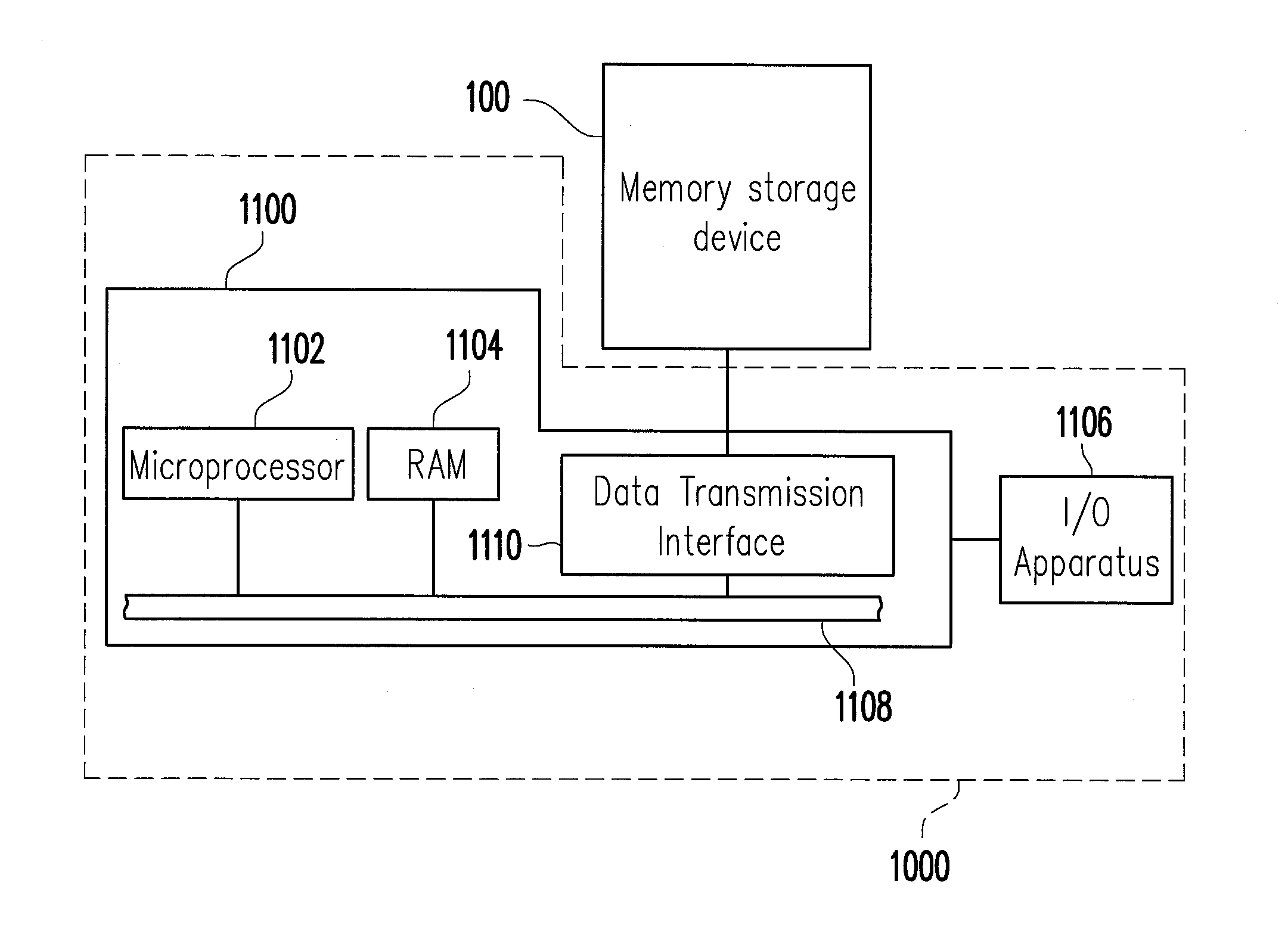
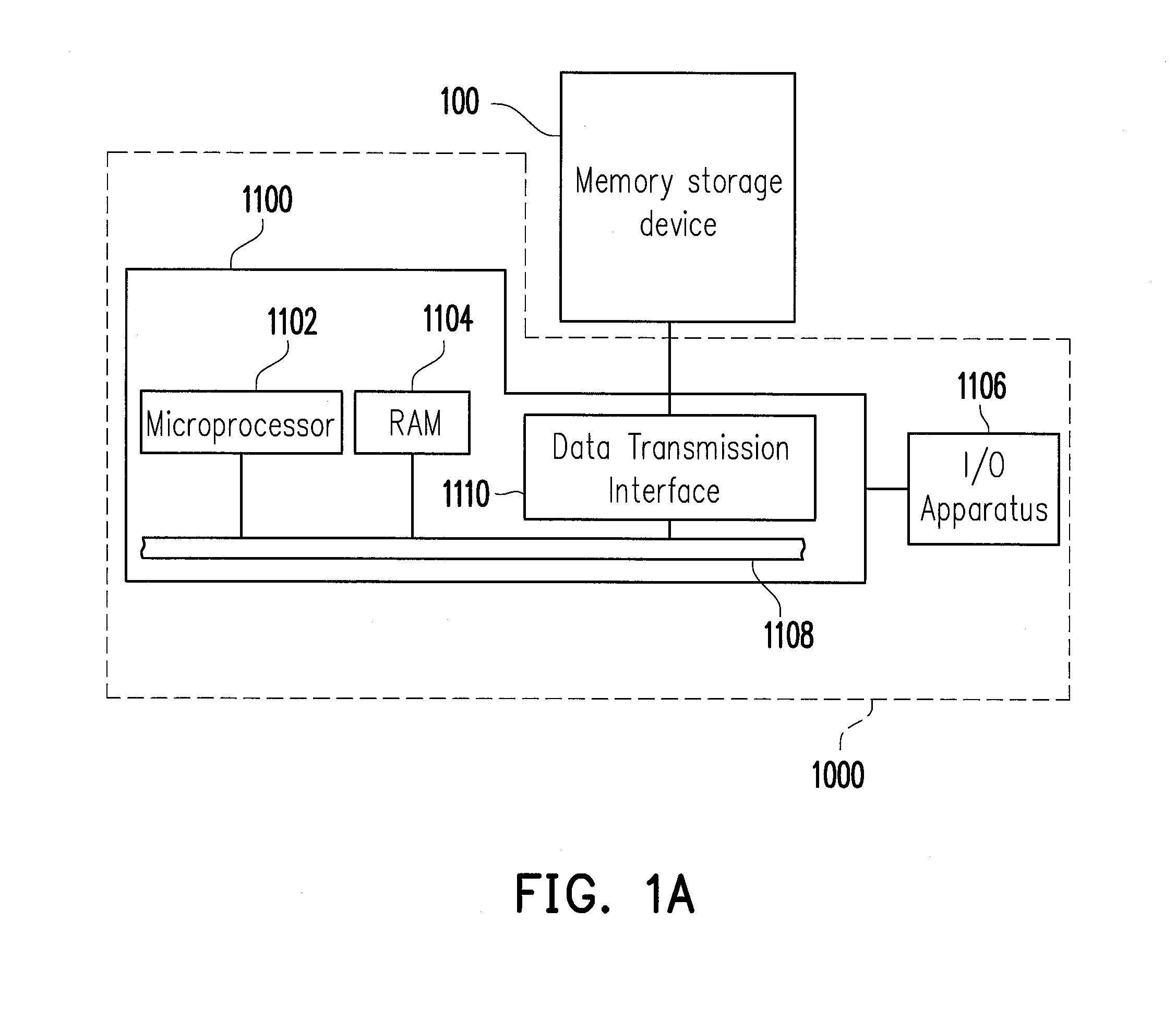
[0046]FIG. 1A illustrates a host system and a memory storage device according to a first exemplary embodiment.

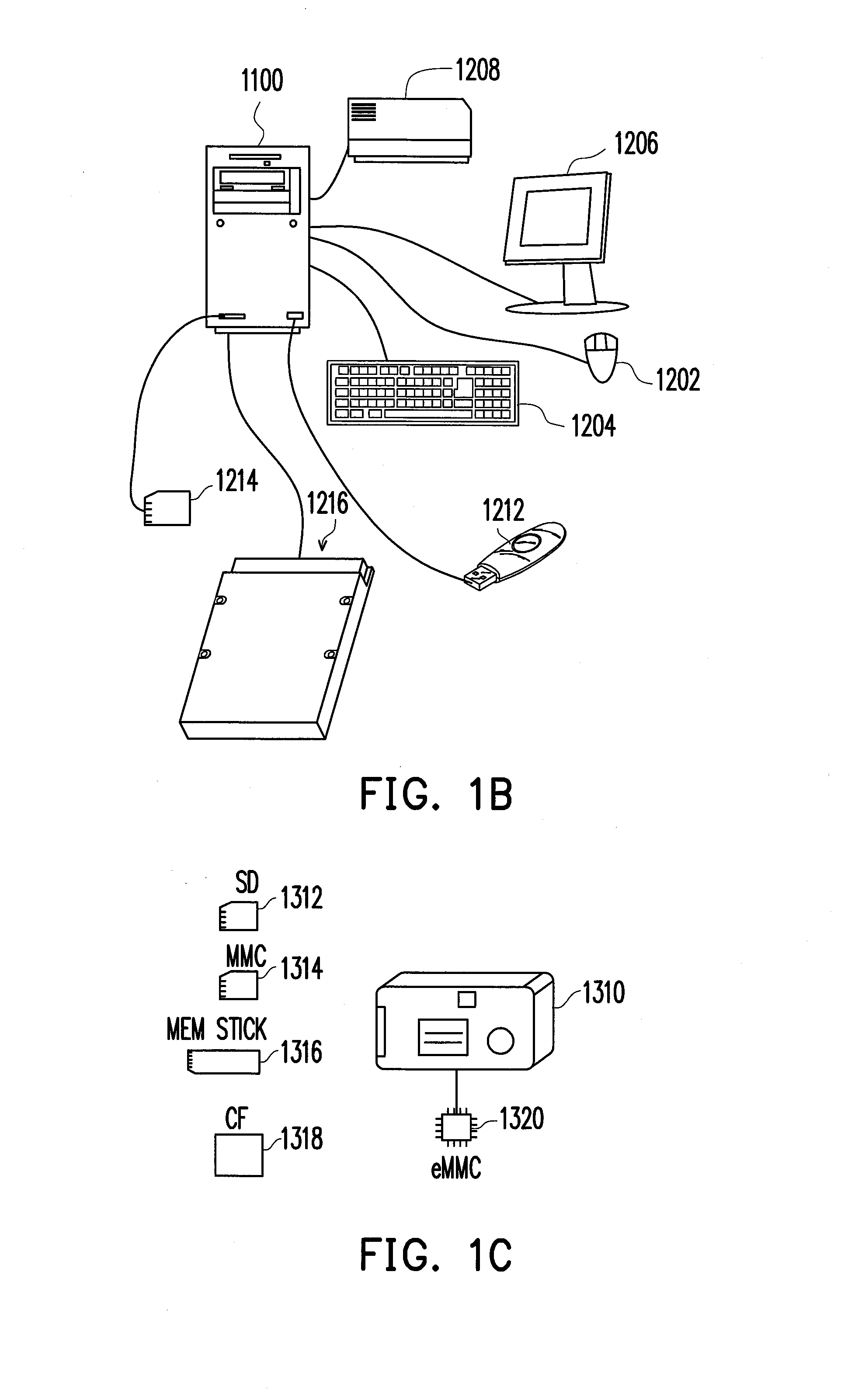
[0047]With reference to FIG. 1A, a host system 1000 in most cases includes a computer 1100 and an input / output (I / O) device 1106. The computer 1100 includes a microprocessor 1102, a random access memory (RAM) 1104, a system bus 1108, and a data transmission interface 1110. The I / O device 1106 includes a mouse 1202, a keyboard 1204, a display 1206, and a printer 1208, as shown in FIG. 1B. It should be understood that, the devices depicted in FIG. 1B is not construed as limitations to the I / O device 1106, and the I / O device 1106 may further include other d...

second exemplary embodiment

[0107]The second exemplary embodiment is similar to the first exemplary embodiment, and differs that the rewritable non-volatile memory module of the memory storage device being is a multi level cell (MLC) NAND flash memory module. Namely, each of the physical blocks in the rewritable non-volatile memory module has a plurality of physical page sets, and each of the physical page sets merely has a lower physical page and an upper physical page.

[0108]FIG. 12 is a schematic diagram illustrating a memory storage device according to the second exemplary embodiment.

[0109]With reference to FIG. 12, a memory storage device 1200 includes the connector 102, a memory controller 1204, and a rewritable non-volatile memory module 1206, in which the function of the connector 102 has been described as above and will not repeated hereinafter.

[0110]The memory controller 1204 is configured for executing a plurality of logic gates or control instructions implemented in a form of hardware or firmware an...


PUM


Abstract

A data writing method for a memory storage device having physical unit unions is provided, wherein each of the physical unit unions includes upper physical units and lower physical units. The method includes partitioning the physical unit unions into a storage area including a data area and a spare area; configuring logical units for mapping to the physical unit unions of the data area; and receiving update data from a host system. The method also includes: selecting several physical unit unions from the spare area as buffer physical unit unions; writing the update data only to a part of each of the buffer physical unit unions; and moving the update data from buffer physical unit unions to the storage area by using a copy procedure. Therefore, the time of performing a write command can be shorten and the lifespan of the memory storage device can be prolonged effectively.

Description

CROSS-REFERENCE TO RELATED APPLICATION[0001]This application claims the priority benefit of Taiwan application serial no. 101109526, filed on Mar. 20, 2012. The entirety of the above-mentioned patent application is hereby incorporated by reference herein and made a part of this specification.BACKGROUND[0002]1. Technology Field[0003]The present invention is directed to a data writing method for a rewritable non-volatile memory module, a memory controller and a memory storage device using the method.[0004]2. Description of Related Art[0005]Along with the widespread of digital cameras, cell phones, and MP3 in recently years, the consumers' demand for storage media has increased drastically. Since a rewritable non-volatile memory has the characteristics of non-volatility of data, low power consumption, small volume, non-mechanical structure, and fast reading and writing speed, the rewritable non-volatile memory is the most adaptable memory applied in a portable electronic product, e.g.,...

Claims


Application Information

Patent Timeline
IPC IPC(8): G06F12/02
CPCG06F12/0246G06F2212/7203G06F2212/1036G06F2212/1016
Inventor TAN, KHENG-CHONGCHUA, LAI-HOCK
Owner PHISON ELECTRONICS
Why Eureka
Try Eureka