Eureka AIR delivers breakthrough ideas for toughest innovation challenges, trusted by R&D personnel around the world.

Conductive powder, conductive material containing the same, and method for producing the same

a technology of conductive powder and conductive material, which is applied in the direction of conductors, coupling device connections, transportation and packaging, etc., can solve the problems of weak adhesion between the core particle and the nickel core material, easy damage to the protruding portion, and inability to maintain integrity between the two parts, so as to achieve the effect of higher conductivity

Active Publication Date: 2013-10-03
NIPPON CHECMICAL IND CO LTD
View PDF6 Cites 18 Cited by
  • Summary
  • Abstract
  • Description
  • Claims
  • Application Information

AI Technical Summary

Benefits of technology

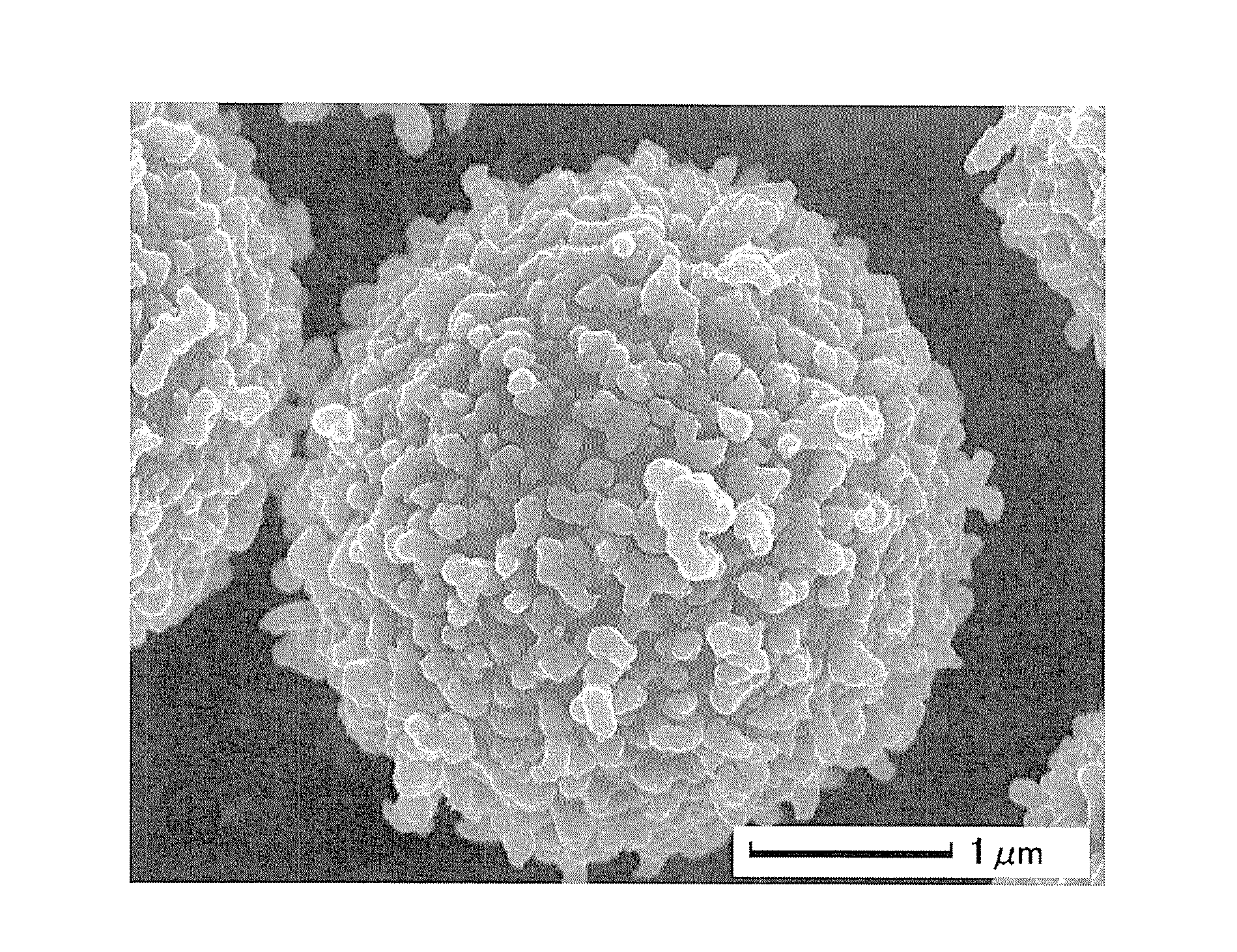
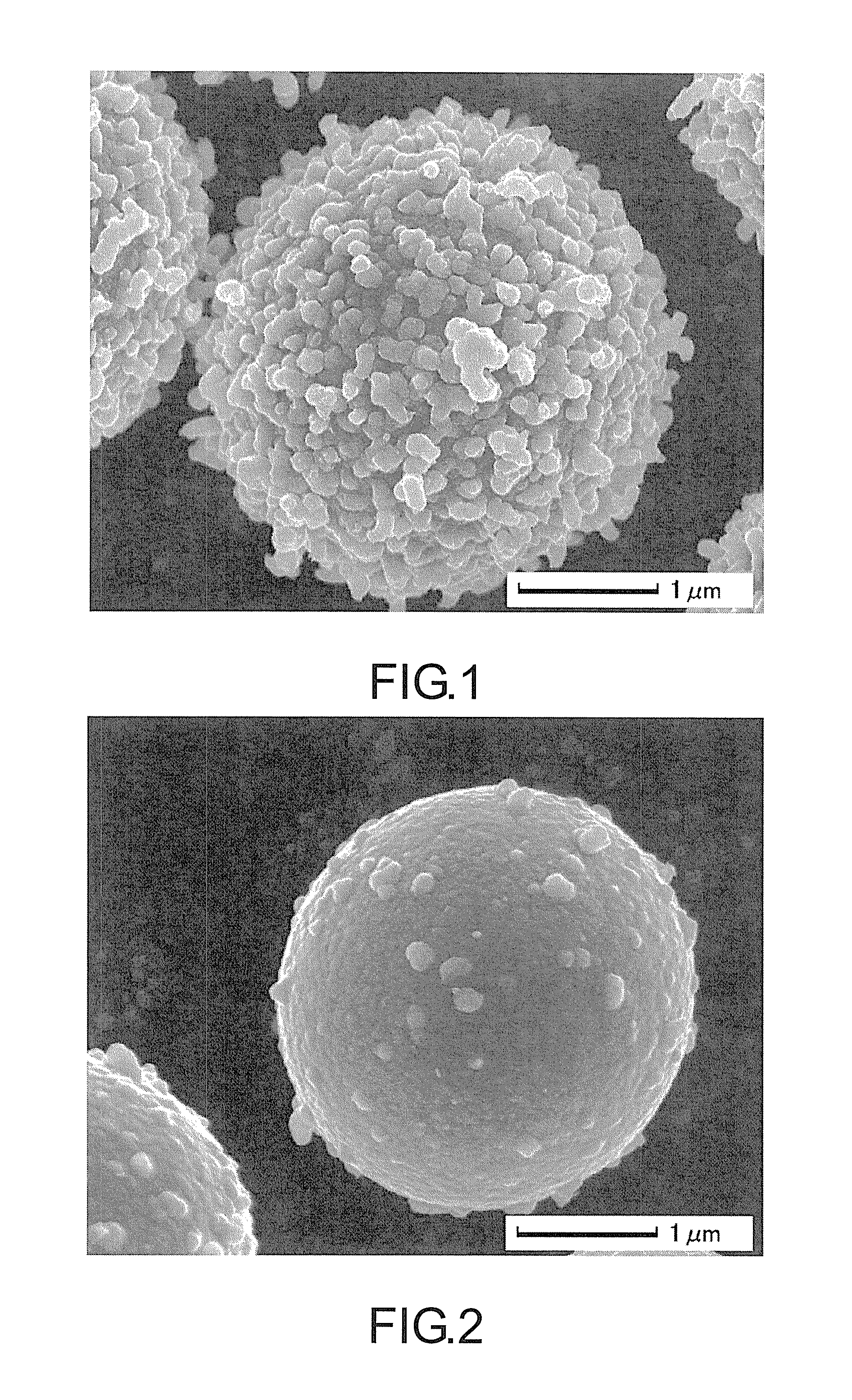
The patent text explains that the conductive powder in the invention has higher conductivity compared to conventional powders because its particles are linked in a row to form a particle chain.

Problems solved by technology

However, in the conductive particle obtained with this method, the adhesion between the core particle and the nickel core material is weak, and integrity is absent between the nickel film coated on the surface of the core particle and the protrusions.
Hence, the protrusions are easily damaged when a pressure is applied to the conductive particle.

Method used


Image

  • Conductive powder, conductive material containing the same, and method for producing the same
  • Conductive powder, conductive material containing the same, and method for producing the same
  • Conductive powder, conductive material containing the same, and method for producing the same

Examples


examples

[0090]This invention will be further explained with the examples, which are however not intended to limit the scope of this invention.

example 6

[0095]An electroless gold plating liquid was prepared, containing 10 g / L of EDTA-4Na, 10 g / L of disodium citrate and 2.9 g / L of gold potassium cyanide (2.0 g / L of Au). Two liters of the gold plating liquid was heated to 79° C., and was added with 10 g of the conductive particle obtained in Example 1 while being stirred. An electroless plating treatment was thus conducted to the surface of the particle for 20 minutes. After the treatment was completed, the solution was filtered, and the filtrate was repulp water-cleaned three times and then dried in a vacuum dryer at 110° C. Thereby, a gold plating coating treatment was performed on the nickel-phosphorus alloy film.

example 7

[0096]An electroless pure palladium plating liquid was prepared, containing 10 g / L of ethylenediamine, 10 g / L of sodium formate, 20 g / L solution of tetraamminepalladium chloride (Pd(NH3)Cl2) (2 g / L of palladium) and 100 ppm of carboxymethyl cellulose (molecular weight: 250000; etherification degree: 0.9). Then, 1.3 L of the palladium plating liquid was heated to 70° C., and 10 g of the nickel-coated particle obtained in Example 1 was added under stirring. An electroless plating treatment was then conducted to the surface of the particle for 30 minutes. After the treatment was completed, the solution was filtered, and the filtrate was repulp water-cleaned three times and then dried in a vacuum dryer at 110° C. Thereby, a palladium plating coating treatment was performed on the nickel-phosphorus alloy film.

[0097][Evaluation of Physical Properties]

[0098]For the conductive particles in the Examples and Comparative Examples, the mean particle size of conductive particles, the nickel film...


PUM

PropertyMeasurementUnit
particle sizeaaaaaaaaaa
molar ratioaaaaaaaaaa
particle sizeaaaaaaaaaa

Abstract

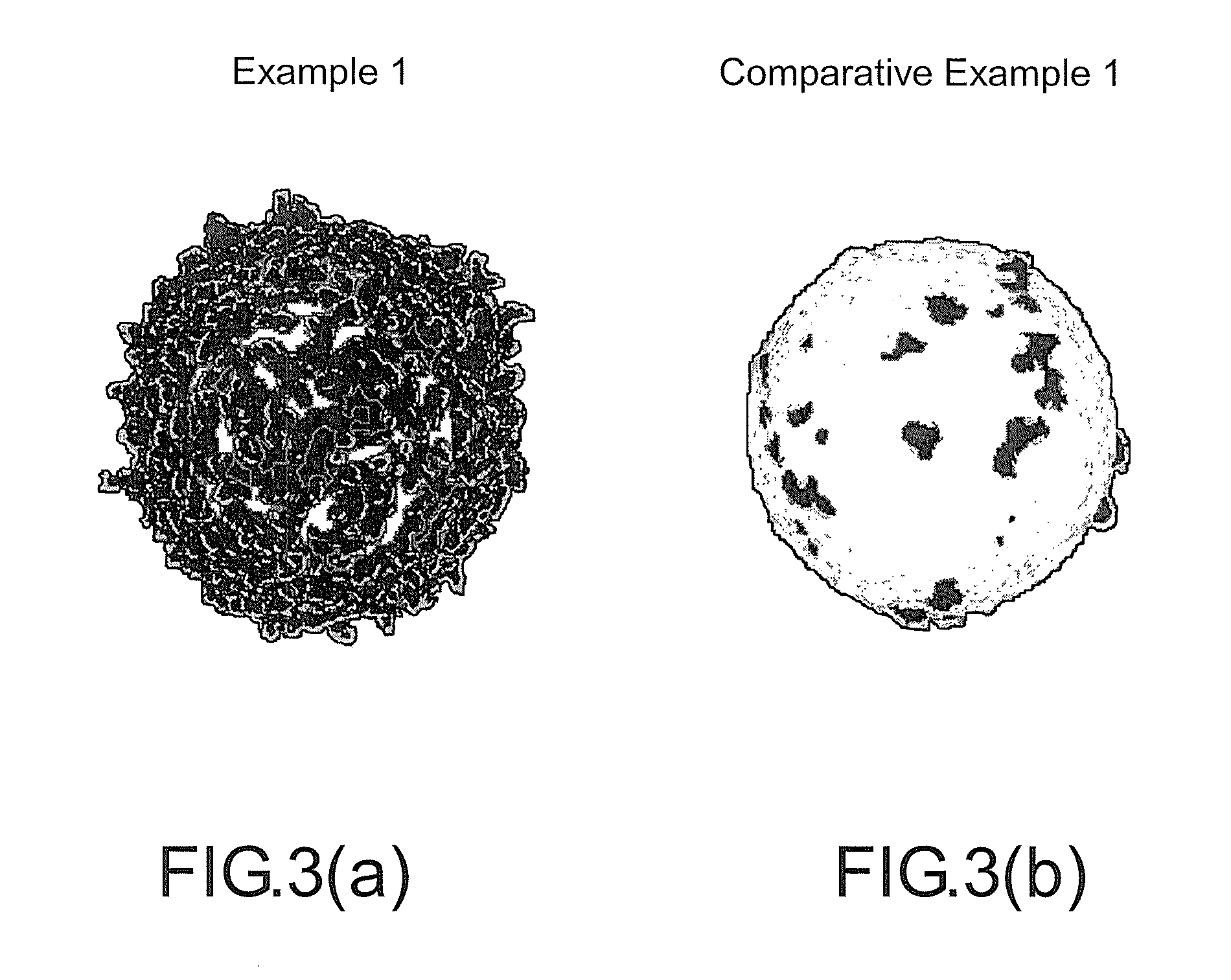
A conductive powder improving various performances as compared to conventional conductive powders is described. The conductive power includes conductive particles, each of which have a metal or alloy film formed on the surface of a core particle. The conductive particle has thereon protrusions protruding from the surface of the film. Each protrusion includes a particle chain including particles of the metal or alloy linked in a row. It is preferred that the metal or alloy is nickel or a nickel alloy. It is also preferred that the ratio of the total area of the exposed portions of the film to the projection area of the conductive particle is 60% or less.

Description

BACKGROUND OF THE INVENTION[0001]1. Field of Invention[0002]This invention relates to a conductive powder and a conductive material containing the same, and also relates to a method for producing a conductive powder.[0003]2. Description of Related Art[0004]The applicant had proposed a conductive powder for electroless plating that has protrusions of nickel or a nickel alloy on its surface (see Patent Document 1). The plating powder exhibits good conductivity due to the effects of the fine protrusions.[0005]In addition to the technique, Patent Document 2 proposed a conductive particle having protrusions, which is obtained by adhering a nickel core material with a particle size of 50 nm to the surface of a core particle with a particle size of 4 μm and then conducting electroless plating of nickel. However, in the conductive particle obtained with this method, the adhesion between the core particle and the nickel core material is weak, and integrity is absent between the nickel film c...

Claims


Application Information

Patent Timeline
Patent Type & Authority Applications(United States)
IPC IPC(8): H01B1/02
CPCH01R13/03H01B1/026H01R13/2414H01B1/02Y10T428/2991
Inventor MATSUMOTO, CHIHIROOYAMADA, MASAAKI
Owner NIPPON CHECMICAL IND CO LTD
Why Eureka
Eureka Blog
Learn More