Renewable energy extraction device tolerant of grid failures

a renewable energy and grid technology, applied in the direction of electric generator control, greenhouse gas reduction, gearing, etc., can solve the problems of accelerating quickly beyond synchronous speed, substantial problem of electricity generators, and occasionally failing electric grids, so as to reduce the maximum absorbable torque of generators

Inactive Publication Date: 2013-10-03
MITSUBISHI HEAVY IND LTD
View PDF7 Cites 26 Cited by
  • Summary
  • Abstract
  • Description
  • Claims
  • Application Information

AI Technical Summary

Benefits of technology

[0050]Typically, the controller controls the rate of displacement of the hydraulic motor and therefore the torque generated by the hydraulic motor so that the torque generated by the hydraulic motor does not exceed the maximum absorbable torque.
[0051]The energy extraction device preferably has a fault response operating mode in which the controller reduces the rate of displacement of the hydraulic motor and therefore the torque generated by the hydraulic motor responsive to detection of a fault which reduces the maximum absorbable torque of the generator. In the fault response operating mode, the controller ensures the torque generated by the hydraulic motor does not exceed the maximum absorbable torque of the generator. Typically, the controller substantially reduces the rate of displacement of the hydraulic motor in the fault response operating mode, for example, such that the rate of displacement is less than 25% per unit time than the rate of displacement which would otherwise occur.

Problems solved by technology

Electricity grids occasionally fail, for example, due to lightning strikes, pylons falling down due to high winds, errors or fault currents.
This presents a substantial problem for electricity generators.
As the rotor remains driven by the prime mover, the rotor will quickly accelerate beyond synchronous speed and pole slip could occur very quickly.
The resulting transient forces are sufficiently violent to lead to a serious risk of damage to the generator or the mechanical connection between the prime mover and the generator rotor.
A further problem can arise when the electricity grid is restored.
In this case, the load angle may initially not be optimal given the torque applied to the rotor by the prime mover, and / or the frequency of rotation of the rotor may be different to the frequency of the electrical grid.
Again, violent transient forces or currents may act, leading to the risk of serious damage.
This problem becomes a greater risk the longer that a fault in the electricity grid remains.
Thus, when a fault has occurred, most prior art devices are disconnected from the electricity grid by a circuit breaker and a lengthy process of re-synchronisation and frequency matching with the grid must be carried out before they can be reconnected.
The electricity grid will therefore suffer a shortage of power during the re-synchronisation and frequency matching, which in some extreme cases has caused electricity grids to fail to recover from such faults.
As a result of these issues it is common not to connect the generator armature directly to the electricity grid.
However, these are expensive and reduce overall reliability.

Method used


Image

  • Renewable energy extraction device tolerant of grid failures
  • Renewable energy extraction device tolerant of grid failures
  • Renewable energy extraction device tolerant of grid failures

Examples


Embodiment Construction

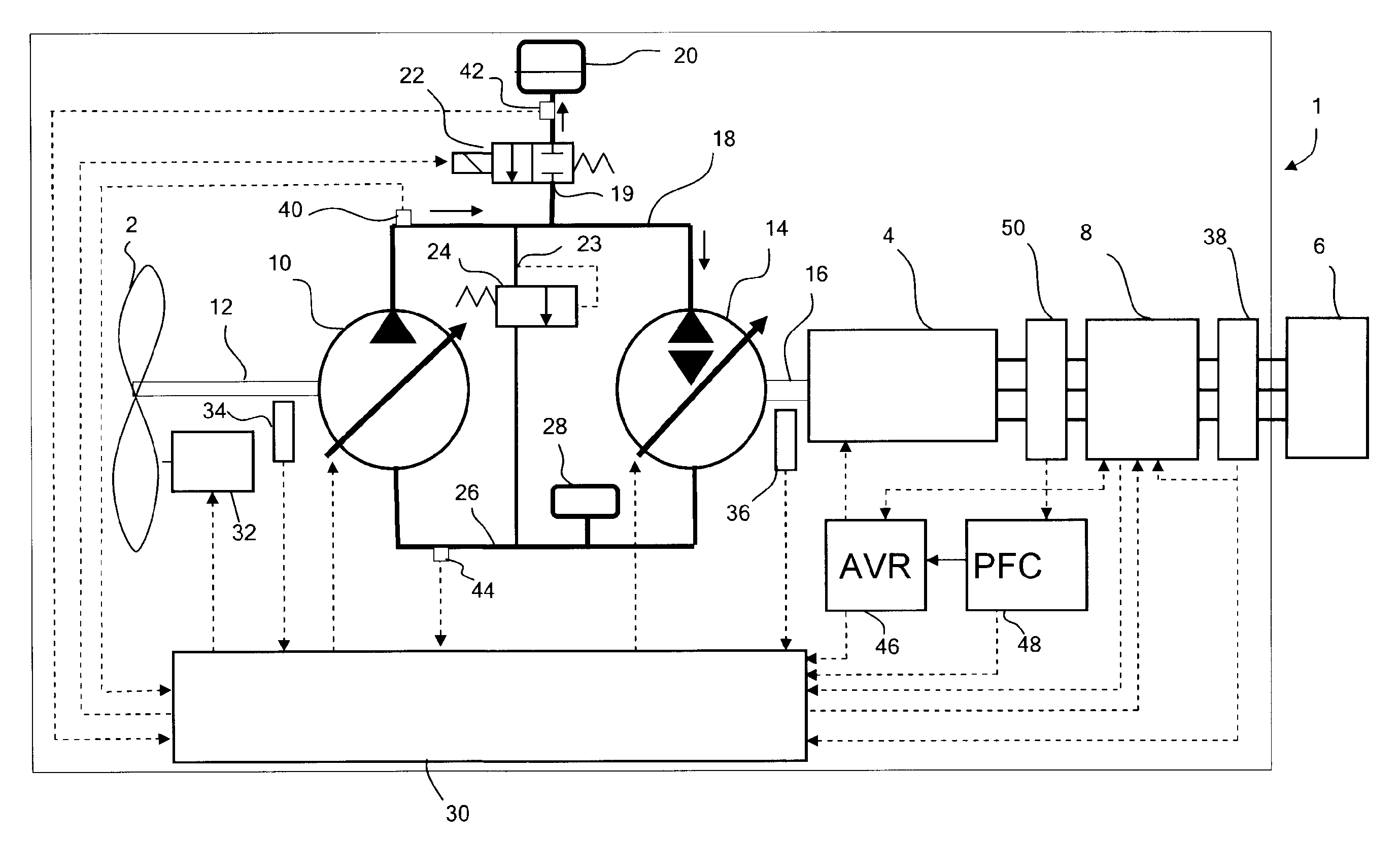
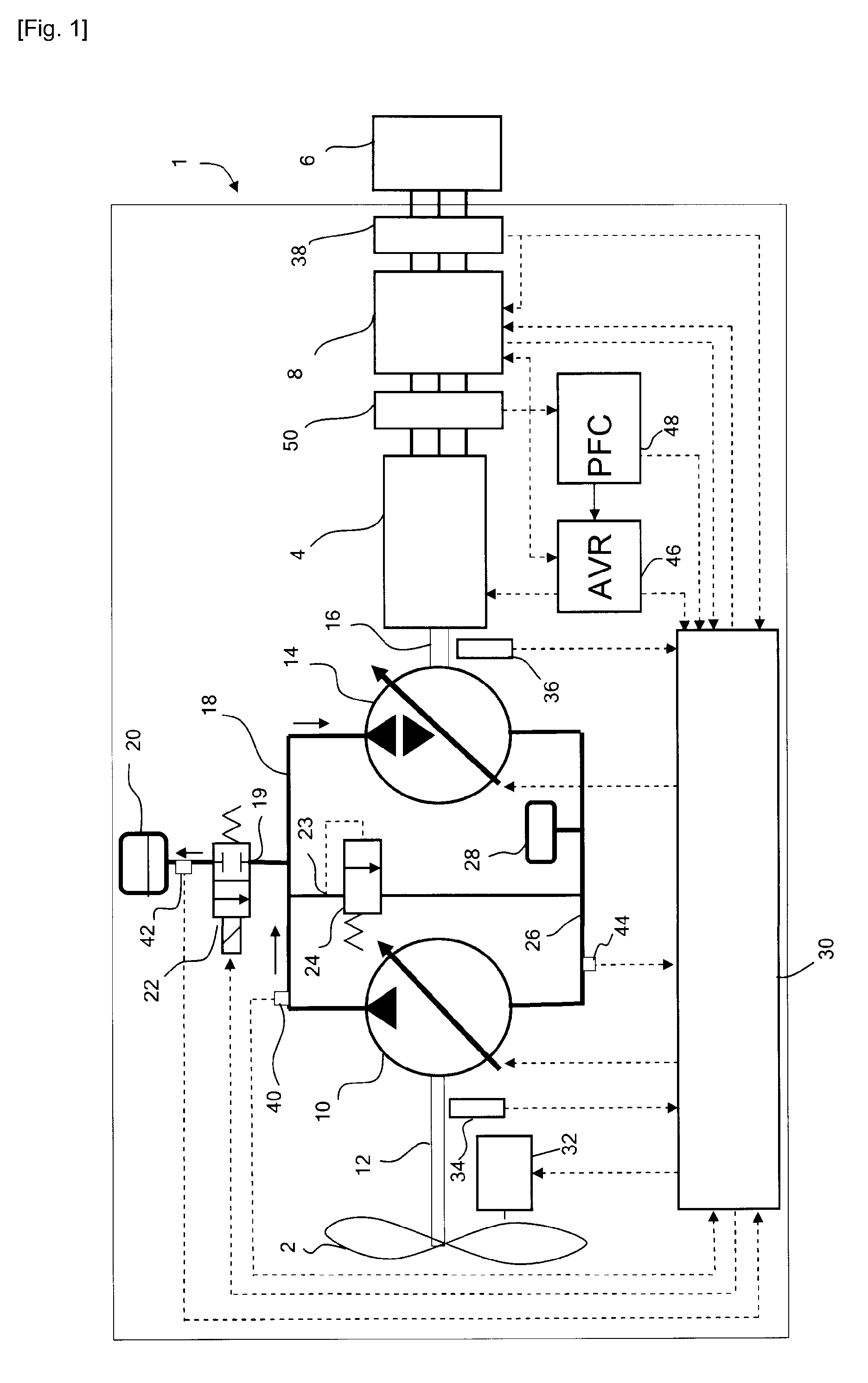
[0078]With reference to FIG. 1, a wind turbine generator 1 comprises a variable-pitch turbine 2 and a synchronous electrical generator 4. The electrical generator is connected to a 3-phase grid 6 (typically operating at 50 Hz or 60 Hz), through a synchronising circuit breaker 8. The connection is effectively a direct connection, without significant buffering capacity.

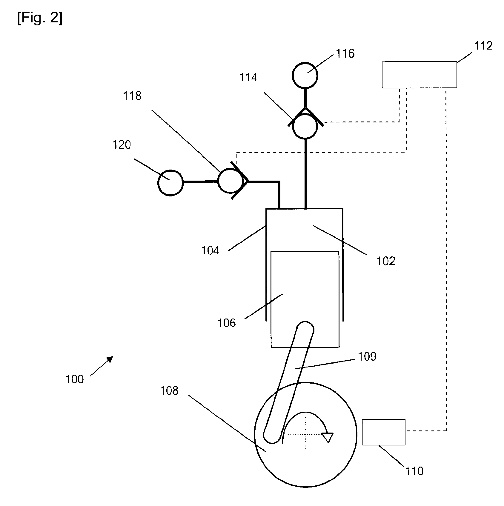
[0079]Wind energy from the turbine is transmitted to the electrical generator through a hydraulic transmission. The hydraulic transmission includes a variable-displacement hydraulic pump 10 drivably connected to the turbine by a driveshaft 12, and a variable-displacement hydraulic motor 14 connected to the rotor of the electrical generator by a further drive shaft 16. Further details of the variable-displacement hydraulic pump and motor are discussed below, with reference to FIG. 2.

[0080]A pressurised fluid manifold 18 (functioning as the high-pressure transmission manifold) extends from the outlet of the hydraulic pump...


PUM


Abstract

A renewable energy extraction device, such as a wind turbine generator includes a turbine driving a hydraulic pump and a variable displacement hydraulic motor driving an electrical generator connected directly to an electricity grid. The hydraulic motor employs electronically controlled valves operated to select the net displacement of working chambers of the hydraulic motor on each successive cycle of working chamber volume. In the event of an electric grid fault causing the maximum absorbable torque of the electrical generator to collapse, the electronically controlled valves are controlled to substantially reduce the rate of displacement of working fluid by the hydraulic motor, rapidly reducing the torque exerted on the generator rotor. This has the benefit of avoiding pole slip which could otherwise cause serious damage. During the fault, the rate of displacement of working fluid by the hydraulic motor is controlled to maintain the phase and frequency of rotation of the generator rotor in synchrony with the electricity grid so that electricity generation can resume rapidly once the grid failure is rectified. Excess working fluid displaced by the hydraulic pump is stored in an accumulator. When the maximum amount has been stored pressurised fluid is discharged through a throttle to avoid damage but maintain pressure within the hydraulic transmission so that electricity generation can resume rapidly if the grid failure is rectified. If the fault persists, the turbine blades are feathered to reduce power input and if the fault persists for a further period of time, the energy extraction device shuts down.

Description

TECHNICAL FIELD[0001]The present invention relates to the field of energy extraction devices for extracting energy from a fluctuating renewable source, such as wind turbines for extracting energy from the wind, which include a hydraulic transmission and an electrical generator driven by a hydraulic motor.BACKGROUND ART[0002]Wind turbines, and other energy extraction device for generating electricity from a renewable energy source use extracted energy to rotate a prime mover which is coupled to an electrical generator rotor. Energy from the electrical generator is directed to an electricity sink, usually an alternating current (AC) electricity grid which includes one or more electrical loads.[0003]Although the present invention relates to energy extraction devices used to drive electrical generators of a range of different types, issues concerning the invention will be illustrated with reference to the example of a synchronous generator. The rotor of a synchronous generator rotates a...

Claims


Application Information

Patent Timeline
Patent Type & Authority Applications(United States)
IPC IPC(8): H02P9/06H02P9/00
CPCF03D9/001F03D9/003F03D11/02Y02E10/725H02P9/006H02P9/06Y02E10/722F05B2260/406F03D15/00F03D9/28F03D9/255Y02E10/72Y02E60/16Y02P80/10Y02E70/30F16H39/20F16H61/4192F16H61/472F16H61/478F03G7/08H02N11/00Y02B10/30F03D15/20F03D9/17
Inventor TAYLOR, JAMIEFIELDING, MICHAELCALDWELL, NIALL
Owner MITSUBISHI HEAVY IND LTD
Why Eureka
Try Eureka