

Scanned-Spot-Array EUV Lithography System
- Summary
- Abstract
- Description
- Claims
- Application Information
AI Technical Summary
Benefits of technology
Problems solved by technology
Method used
Image


Examples
Embodiment Construction
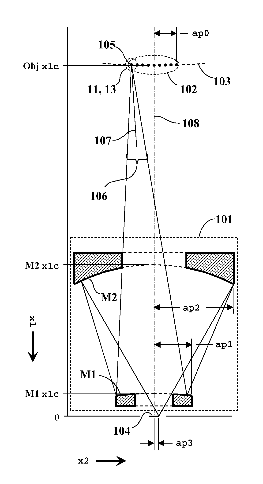
[0048]FIGS. 1A and 1B conceptually illustrate the EUV projection optics 101, which comprise axially-symmetric, annular, aspheric mirrors M1 and M2 (shown in cross section) in a flat-image Schwarzschild configuration. (See p. 18.15 in Ref. 2.) The mirror surfaces have multilayer EUV reflectance coatings. Spot-generation optics partition incident radiation into separate beams diverging from discrete object spots 102 on an object surface 103. Mirrors M1 and M2 image the object spots onto conjugate image points on an image plane 104 at reduced magnification. The spot-generation optics compensate for geometric point-imaging aberrations in the projection optics, enabling substantially diffraction-limited imaging performance over the full image field. A photosensitive layer at the image plane is raster-scanned as the spots are intensity-modulated to synthesize a high-resolution printed image from the point exposures. (A possible scan pattern is illustrated in the '843 ...
PUM
 Abstract
Description
Claims
Application Information