Nucleic acid nanostructure barcode probes

a technology of nucleic acid and probes, applied in the field of nucleic acid barcode probes, can solve the problem of limited multi-plexing ability of fluorescent imaging

Active Publication Date: 2013-10-03
PRESIDENT & FELLOWS OF HARVARD COLLEGE
View PDF6 Cites 129 Cited by
  • Summary
  • Abstract
  • Description
  • Claims
  • Application Information

AI Technical Summary

Benefits of technology

[0004]The invention provides, inter alia, nucleic acid barcode probes that comprise a nucleic acid nanostructure comprising one or more fluorescently labeled regions that may be stably or transiently bound (and thus labeled) with fluorophore-bearing oligonucleotides. The barcode probes may further comprise a target binding moiety. The invention also provides methods of use for such barcode probes including but not limited to their use in analyte detection assays (e.g., assays for detecting and optionally quantitating one or more analytes). The nature of the fluorescent signals (e.g., the wavelength or “color”, intensity, etc.) and the pattern (or orientation, or arrangement or geometry) of such signals on the barcode can also be used to identify particular analytes in a sample. This facilitates multiplexed assays in which a plurality of analytes are detected simultaneously (or at a minimum with a single sample or a single aliquot from a sample).

Problems solved by technology

A major challenge in modern biology and nanotechnology is to observe, identify and differentiate a large number of different molecular species in real time.
However, the multiplexing ability of fluorescent imaging is limited by the number of spectrally non-overlapping fluorophores available.

Method used


Image

  • Nucleic acid nanostructure barcode probes
  • Nucleic acid nanostructure barcode probes
  • Nucleic acid nanostructure barcode probes

Examples


example 1

Creation of a DNA Barcode

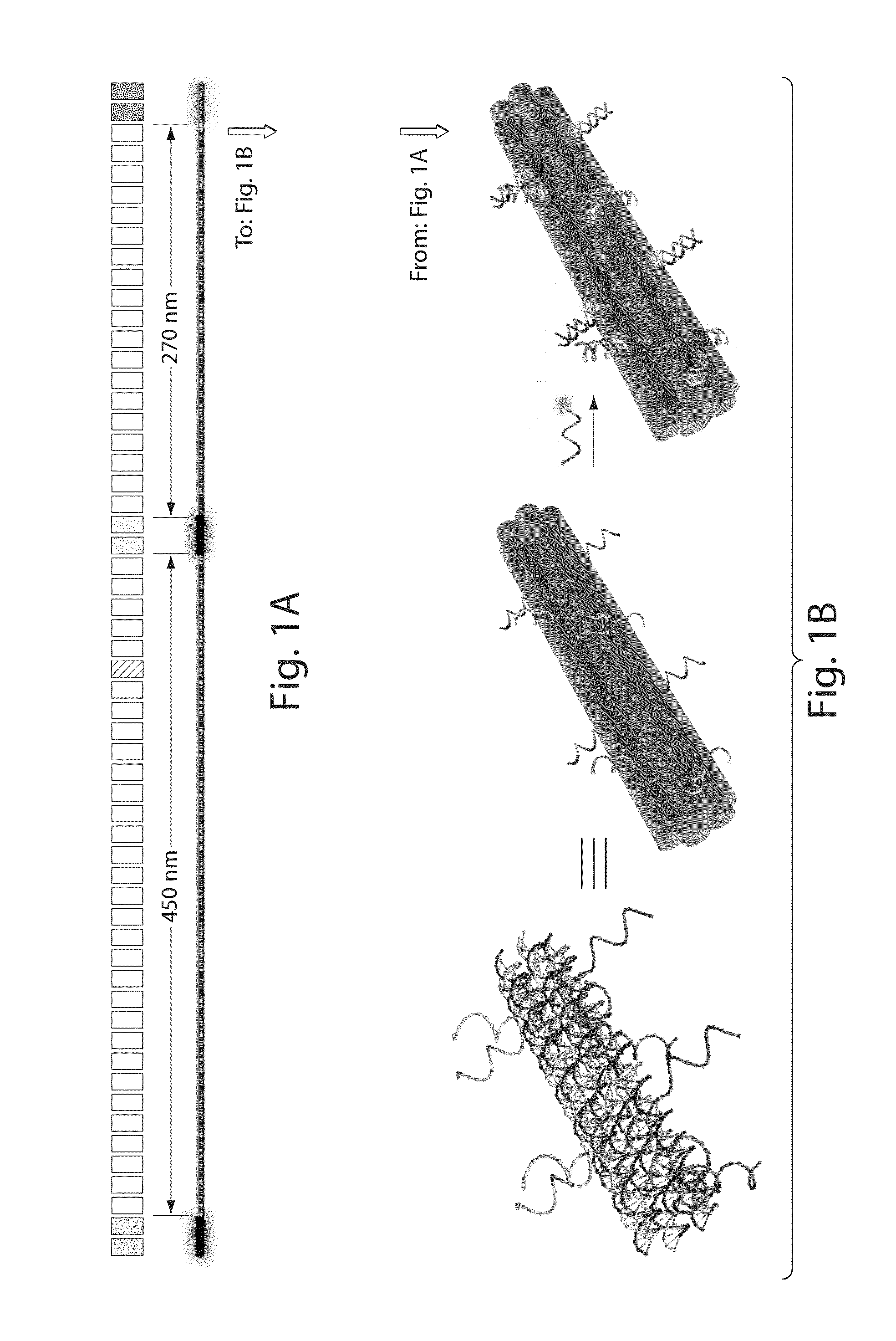
[0083]DNA origami barcode probes were constructed by fluorescently labeling three separate regions of an 800-nm six-helix bundle dimer nanotube (FIG. 1). Each of the approximately 28 nm long fluorescently labeled regions was modified with twelve oligonucleotides attached to one of the three fluorophores (rhodamine-green, Cy3 or Cy5). The DNA origami barcode probe was designed to be asymmetric by placing the first two labeled regions further apart (approximately 460 nm apart) than the last two (approximately 270 nm apart). It is to be understood that other arrangements, including symmetric arrangements, are also contemplated by the invention.

[0084]The main structure of the DNA origami barcode probe is a DNA six-helix bundle nanotube dimer designed using the caDNAno software available at the cadnano website. The sequence of the scaffold strand used for each monomer is provided as SEQ ID NO: 1. The sequences of the staples used in the construction of the DNA or...

example 2

Detection of a Singly-Labeled DNA Barcode Using Fluorescent Microscopy

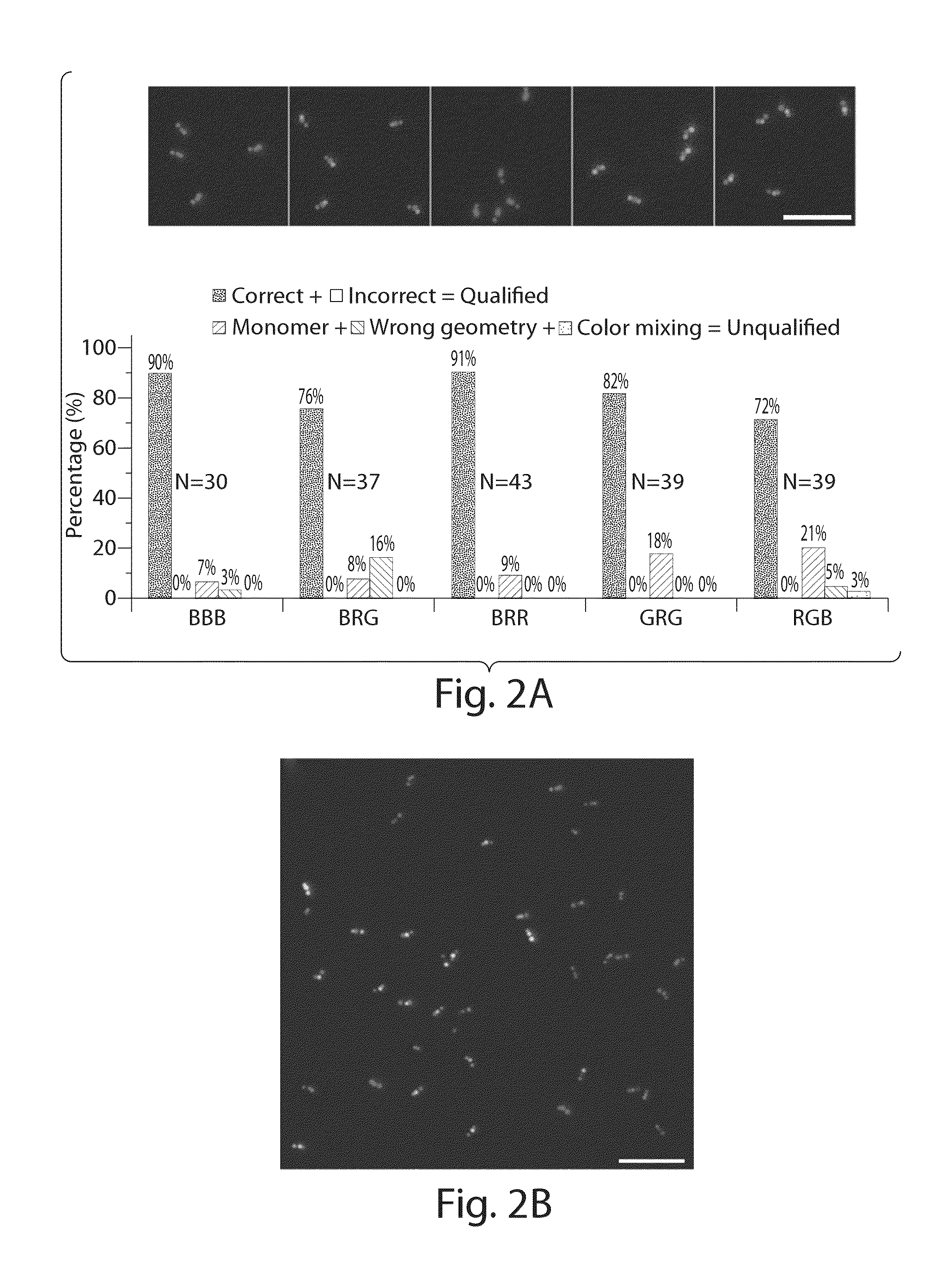
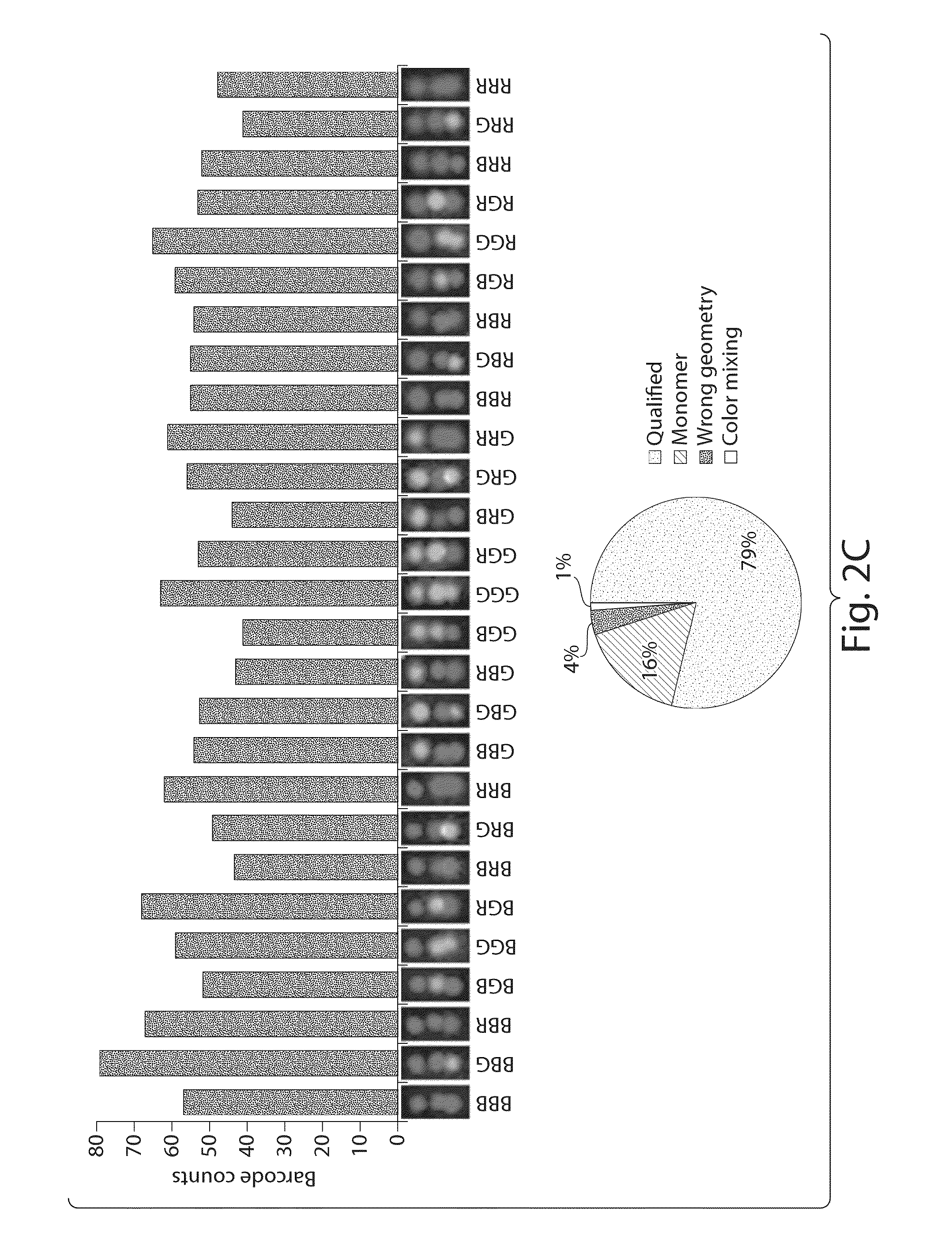
[0089]Two of the monomer nanotubes were folded and fluorescently labeled separately and combined together as described above to yield the nano-barcode. The final product was purified by agarose gel electrophoresis and directly deposited on a glass slide for imaging using a total internal reflection fluorescence microscope (TIRFM). In brief, 5 μL of the purified nano-barcode (˜20 pM) was deposited on a glass slide, sandwiched by a coverslip (No. 1.5, 18×18 mm2, ˜0.17 mm thick) and let sit for 5 minutes before being imaged on a Leica DM16000B TIRFM. The samples were imaged sequentially through three channels, each assigned a false color (blue, green and red). For the blue channel, the 488 nm laser beam was reflected by a dichroic mirror (430 / 505 / 575 / 670) and shined on the sample through a 100× objective (HCX PL APO 100× / 1.47 oil CORR TIRF, Leica). The emission light was collected through the same objective, filtered...

example 3

Detection of an Oligonucleotide Target Using a DNA Barcode Probe

[0097]A 42-nt DNA oligonucleotide target was detected using a DNA origami barcode probe. Two different purified barcodes Green, Red, Green (GRG) with the 21-nt oligonucleotide target capture moiety specific for a 42-nt oligonucleotide target (Target 1, see Table 3 for sequences) and Blue, Red, Green (BRG) without a target capture moiety, were mixed at 1:1 ratio and diluted to 20 pM in folding buffer. Biotin probe specific for Target 1 (0.2 μL of 100 nM) and Target 1 (0.4 μL, of 10 nM) was added to 100 μL of the barcode mixture. In a separate test tube containing 100μL of the barcode mixture, 0.2 μL of 100 nM biotin probe for Target 1 and 0.4 4. of 1× folding buffer was added as a negative control. The above samples were both incubated at 37° C. overnight before being run through separate channels of a micro-fluidic cell with a streptavidin coated glass cover-slip (Xenopore) substrate. Both channels were then washed with...


PUM

PropertyMeasurementUnit
diameteraaaaaaaaaa
distanceaaaaaaaaaa
distancesaaaaaaaaaa

Abstract

Provided herein are, inter alia, barcode probes comprised of transiently or stably fhiorescently labeled nucleic acid nanostructures that are fully addressable and able to be read using standard fluorescent microscope and methods of use thereof including methods of use as detectable labels for probes.

Description

RELATED APPLICATIONS[0001]This application claims the benefit of U.S. Provisional Application Ser. No. 61 / 408358, filed on Oct. 29, 2010, entitled “DNA NANOSTRUCTURE BARCODE PROBES”, the entire contents of which are incorporated by reference herein.REFERENCE TO A COMPACT DISK APPENDIX[0002]A computer program listing is appended to this disclosure and is hereby incorporated herein by this reference. The appendix includes the file programlisting.txt which includes listings for 6ht-v5-1color-1.json and 6ht-v6-2color-1.json.BACKGROUND OF INVENTION[0003]A major challenge in modern biology and nanotechnology is to observe, identify and differentiate a large number of different molecular species in real time. Fluorescent microscopy is a powerful tool for non-destructively and dynamically monitoring many individual molecular events. However, the multiplexing ability of fluorescent imaging is limited by the number of spectrally non-overlapping fluorophores available. There is therefore a gre...

Claims


Application Information

Patent Timeline
Patent Type & Authority Applications(United States)
IPC IPC(8): G01N21/64
CPCB82Y15/00C12Q1/6825G01N21/6486C12Q2563/107C12Q2563/157C12Q2563/185C12Q2565/102C12Q2565/601
Inventor LIN, CHENXIANGLI, CHAOSHIH, WILLIAM M.YIN, PENGJUNGMANN, RALF
Owner PRESIDENT & FELLOWS OF HARVARD COLLEGE
Why Eureka
Try Eureka