Latent heat storage device with phase change material and graphite matrix

a heat storage device and phase change technology, applied in lighting and heating apparatus, charge manipulation, furniture, etc., can solve the problems of difficult to conduct heat into the pcm, pcm is not structurally rigid, and the space in the application is typically very limited

Inactive Publication Date: 2013-10-10
SGL CARBON SE
View PDF7 Cites 20 Cited by
  • Summary
  • Abstract
  • Description
  • Claims
  • Application Information

AI Technical Summary

Benefits of technology

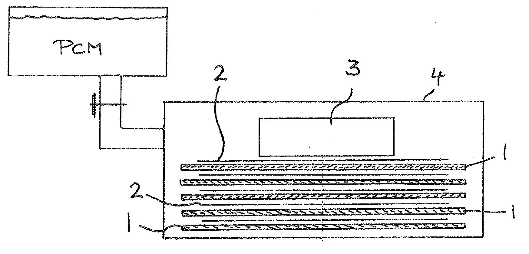
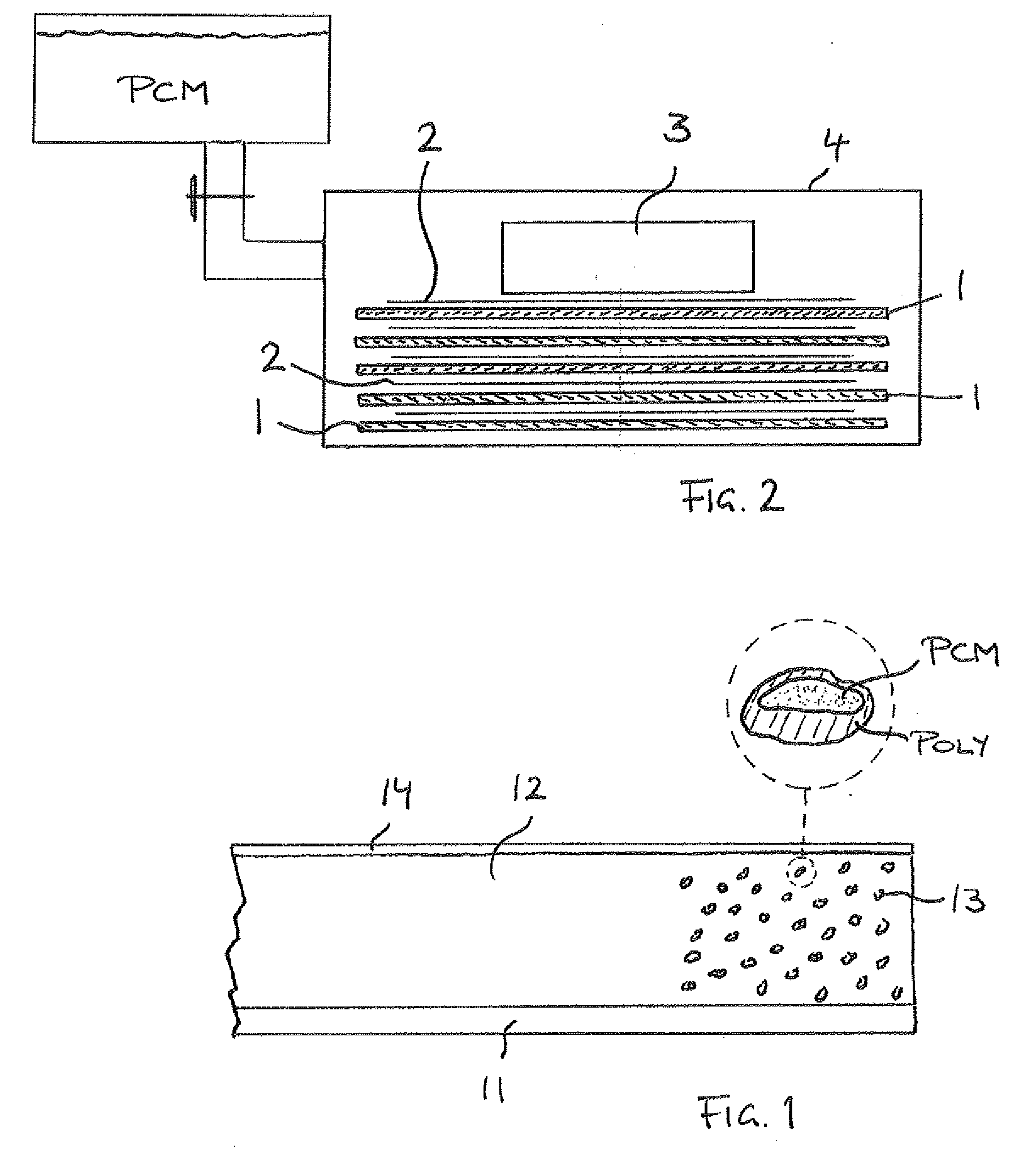
[0009]It is accordingly an object of the invention to provide a latent heat storage device based on PCM / graphite composite material which overcomes the above-mentioned disadvantages of the heretofore-known devices and methods of this general type and which provides for more freedom, relative to the prior art, in terms of structural dimensions, thermal conductivity, and heat storage capacity.

Problems solved by technology

Since the space in the application is typically very limited, it is necessary to provide the cooling by way of very thin materials.
As such, it is technically difficult to conduct the heat into the PCM.
Also, the PCM is not structurally rigid, at least in one of its useful phases.
It is not possible to miniaturize the device to such a degree as to render it suitable for electronic device cooling.
Currently, latent heat storage devices based on the PCM / graphite composite principle are limited in their use since their thickness cannot yet be reduced below certain limits and the mechanical stability of the systems can only be assured with considerable difficulty.

Method used


Image

  • Latent heat storage device with phase change material and graphite matrix
  • Latent heat storage device with phase change material and graphite matrix
  • Latent heat storage device with phase change material and graphite matrix

Examples


production examples

Example 1

PCM on Copper

[0041]4 g of a 5% PVDF solution (vinylidene fluoride polymer) were mixed with 2.3 g of a mixture of Micronal® (PCM, melting temperature ˜25° C., BASF, Germany) and highly expanded graphite (GFG 5) at a ratio of 75% by weight to 25% by weight were mixed together with N-methyl-2-pyrrolidone (2.5 NMP, solvent). The stirring time for the solution was about 1 hour. The mixed solution was coated onto a Cu foil (0.1 mm thick) by means of a doctor blade, the coating thickness being about 250 μm. The coating was subsequently dried at 60° C.

[0042]Then, a high-density graphite foil was glued onto the coating, in order to thereby achieve the high thermal conductivity required of such devices. The thickness of the graphite foil was approx. 0.5 mm and its density was 18 g / cm3 (type L05518Z, SGL Carbon SE). The glue application onto the coating was effected by way of spray adhesive.

example 2

PCM on / in Graphite:

[0043]First we produced a Tylose solution. Distilled water was introduced into a beaker, and 0.75% Tylose MHB 3000 was slowly interspersed with constant stirring. After a stirring time of about 30 minutes, the mixture was left to stand and swell. A batch of a polyvinyl alcohol (PVA) solution was then produced. To this end, distilled water was heated to about 80-90° C., and then 0.75% Mowiol 588 (PVA) was introduced with constant stirring in a laboratory mixer. After a stirring time of about 30 min, all of the PVA granules had dissolved.

[0044]In a next step, the carrier solution was produced from 0.75% Tylose solution and 0.75% PVA solution by mixing. The mixing ratio of the two solutions in this case was 1:1.

[0045]A phase change material proportion was then introduced into the carrier solution. We once more used Micronal® (Tm=25° C.), here in a ratio 1.75:1 (carrier solution to Micronal®). The phase change material was introduced into the solution with the aid of ...

example 3

Impregnated Graphite

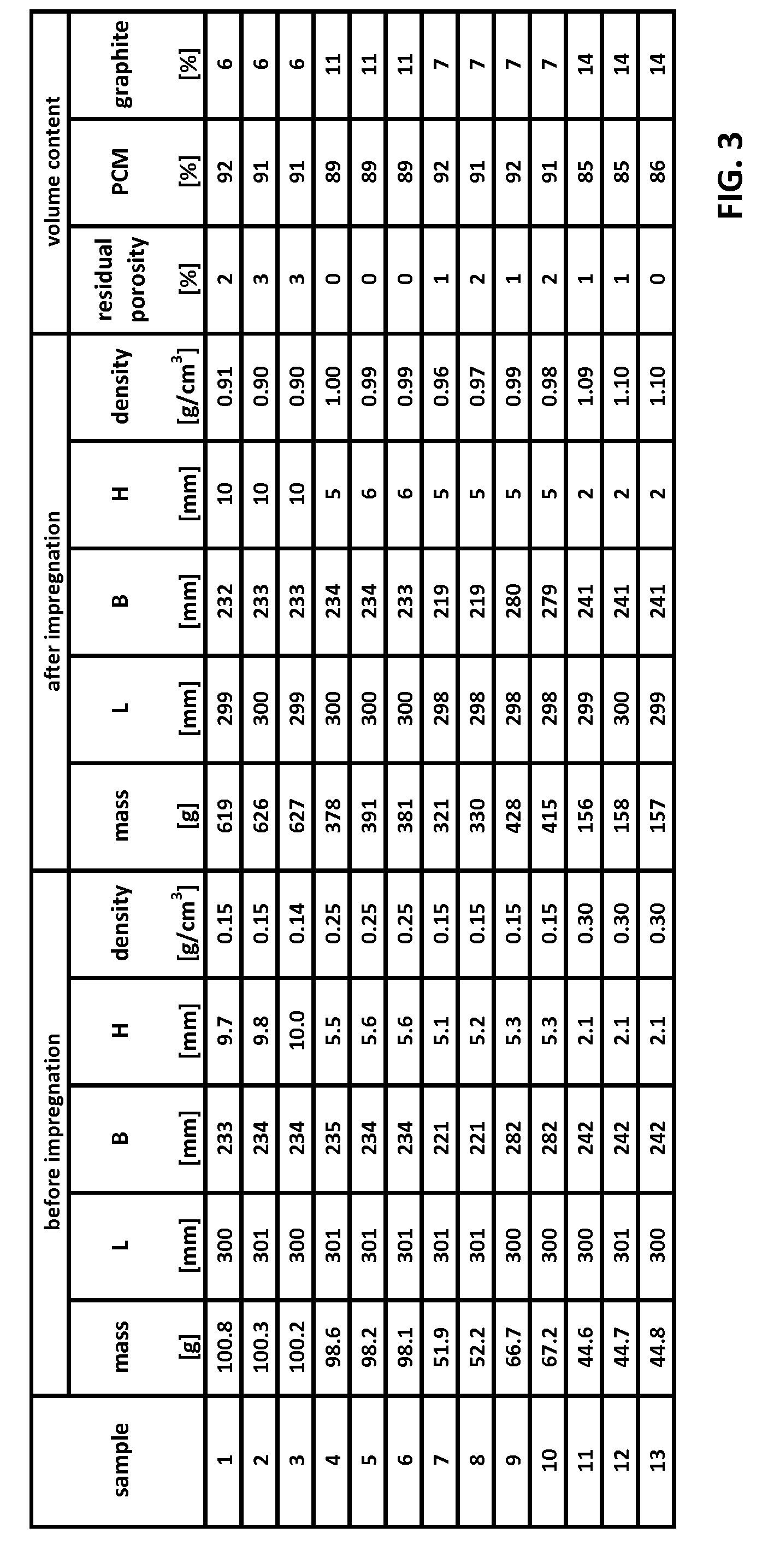
[0050]Here, we were concerned with infiltration properties of certain materials. The development was not limited to the extremely thin dimensions of 1 mm, but blanks and the resultant product assemblies were allowed to have thicknesses between 2 and 10 mm. The base system was formed with substrate blanks with high absorption capacity for infiltration with phase change material (PCM) and proper adhesion of a high-density graphite cover foil.

[0051]The high-density cover foil may also be provided on both planar surfaces and, indeed, it may be used to encase or encapsulate the entire sandwich structure. The graphite plate or graphite sheet can thereby be formed with very large scale perforations in which the PCM may be infiltrated. In its liquid phase, the phase change material cannot escape from the porous graphite substrate because of the protection afforded by the cover foil.

[0052]A variety of different graphite substrates were used for the production of the vari...


PUM

PropertyMeasurementUnit
temperatureaaaaaaaaaa
thicknessaaaaaaaaaa

Abstract

A latent heat storage device is formed with a carrier substrate formed of expanded graphite material. Phase change material is infiltrated in the graphite material. A thin graphite sheet provides for the functional heat conductivity into and out of the carrier substrate. After the phase change material (PCM) is infiltrated in the carrier substrate, a density of the infiltrated carrier substrate exceeds its starting density by a ratio of at least 3:1 or 4:1 or more. The volume dimensions of the infiltrated the carrier substrate remain substantially unchanged. In the alternative, the latent heat storage device may also have a PCM coating layer on a thin carrier substrate, wherein the phase change material is interspersed in a carrier matrix forming the PCM coating layer. The composite device may be very thin.

Description

BACKGROUND OF THE INVENTIONField of the Invention [0001]The invention relates to a heat-conducting device, such as heat sinks and similar cooling structures, and to PCM / graphite composite systems.[0002]Phase change materials (PCM) are capable of storing heat energy in the form of latent heat. The heat content is stored primarily by the conversion of the PCM from one phase to another. Most PCMs thereby change between a liquid phase and a solid phase. The heat transferred into or out of the PCM does not change its temperature; it is referred to as latent heat.[0003]Phase change materials are being increasingly used in cooling systems for electronic devices. Within electronic applications, the cooling of devices is realized through to thin metal sheets, graphite foils or thermal conductive gels. Since the space in the application is typically very limited, it is necessary to provide the cooling by way of very thin materials. In order to combine a heat spreading or heat conducting mater...

Claims


Application Information

Patent Timeline
Patent Type & Authority Applications(United States)
IPC IPC(8): F28D17/00F27D3/00
CPCC09K5/063F28D20/023F28F21/02Y02E60/14
Inventor HUDLER, BASTIANSCHMITT, RAINERFORD, BRIANLANGER, WERNERMECHEN, SYLVIA
Owner SGL CARBON SE
Why Eureka
Try Eureka