High-frequency power supply

Active Publication Date: 2013-10-10
SHIMADZU CORP
View PDF6 Cites 14 Cited by
  • Summary
  • Abstract
  • Description
  • Claims
  • Application Information

AI Technical Summary

Benefits of technology

[0058]As mentioned above, according to the high-frequency power supply of the invention, by using the constant-current conversion circuit, for the abrupt variations in the resistance and inductance of the induction coil occurred when the plasma suddenly disappears and so on, over-current from the output of the half-bridge drive circuit may be automatically avoided without intervention of a control circuit

Problems solved by technology

Moreover, energy loss due to heating of the plasma provides a resistance component of impedance of the induction coil.
However, in the case that the load impedance varies, maintaining the optimum condition all the time by operating the tuning circuit requires a complicated control mechanism an

Method used


Image

  • High-frequency power supply
  • High-frequency power supply
  • High-frequency power supply

Examples


Example

[0064]Below is an explanation for a high-frequency power supply apparatus used in an inductively coupled plasma (ICP) emission spectrometer and serves as one example of the high-frequency power supply of the invention.

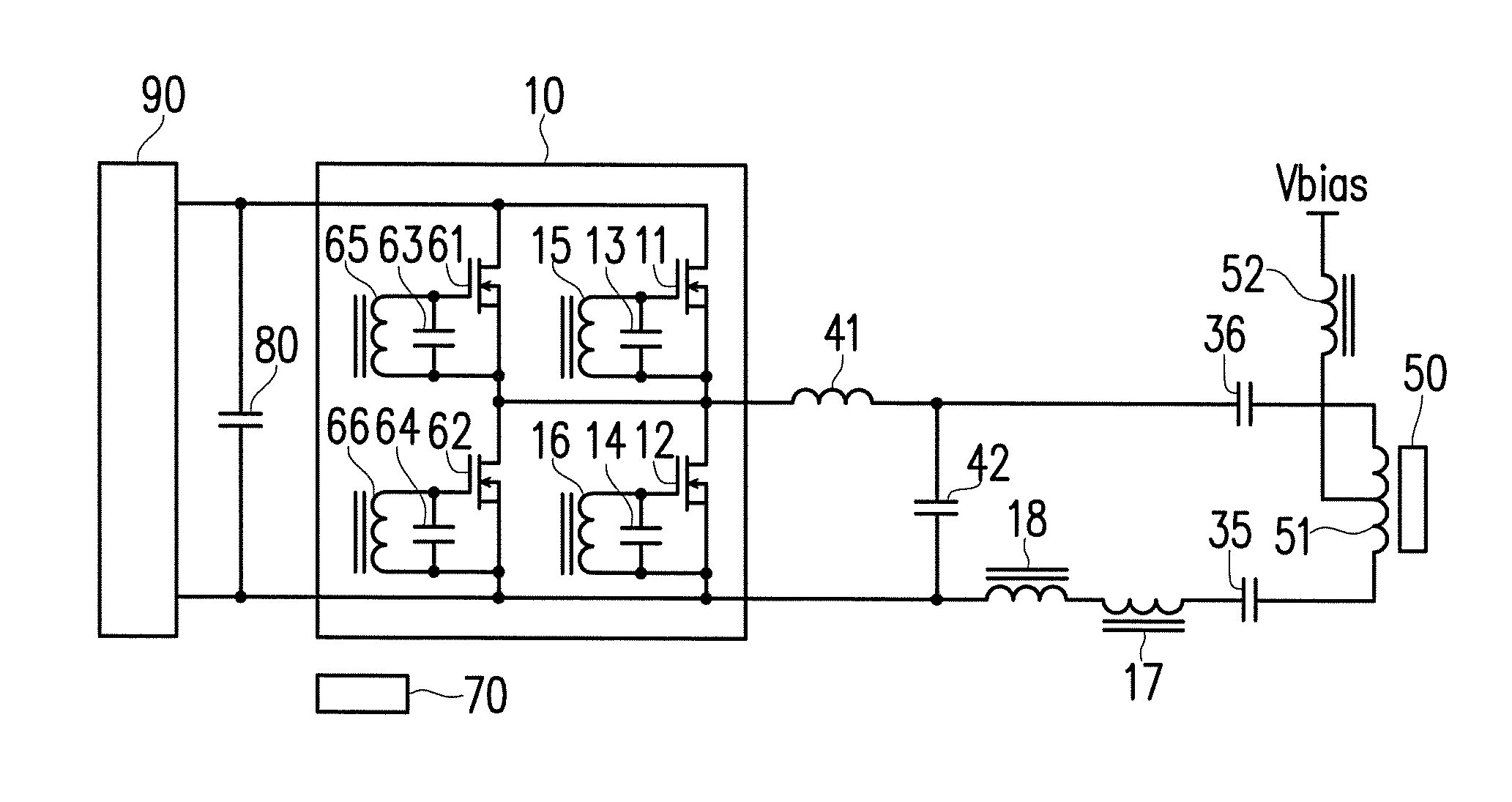
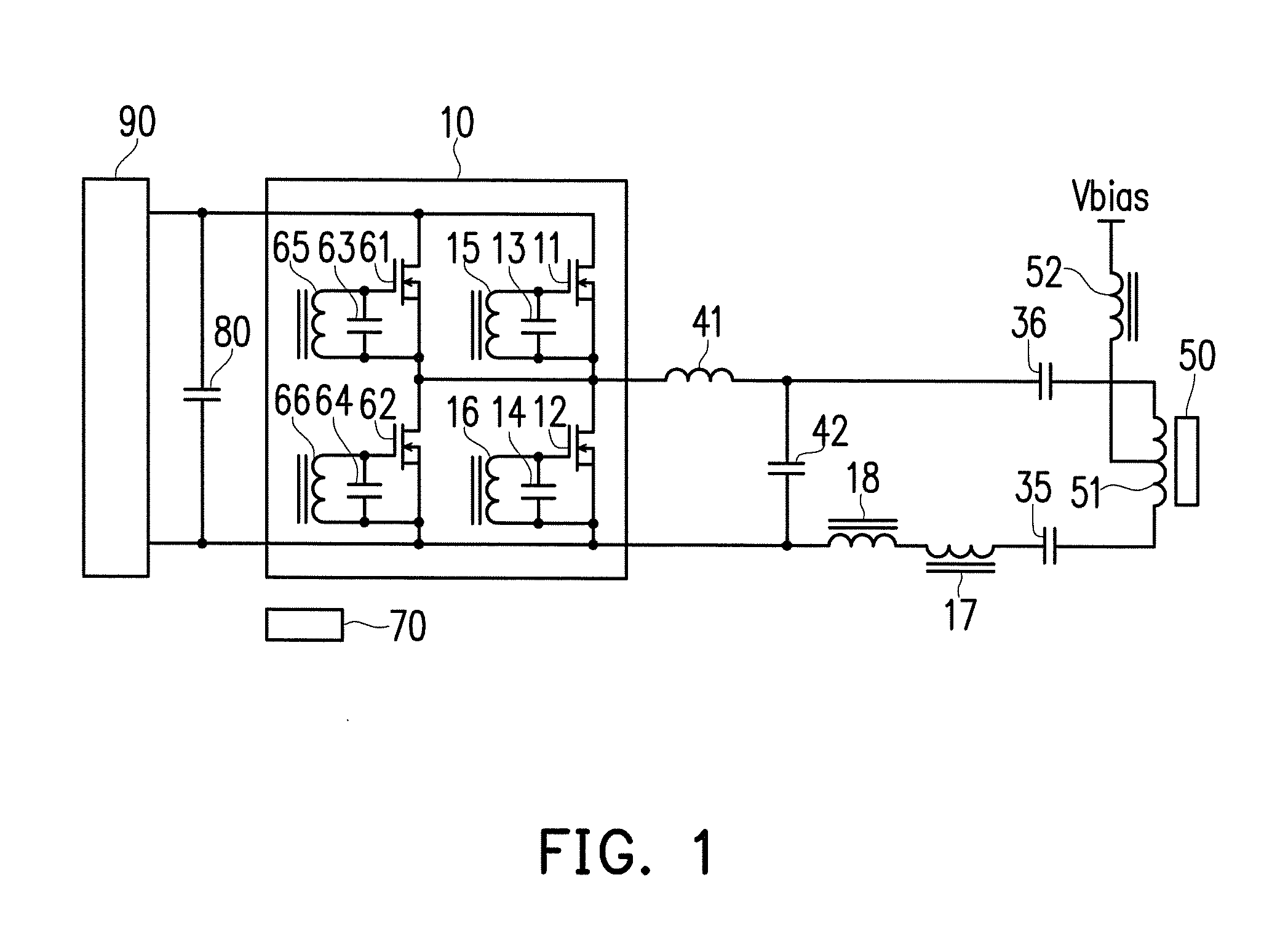
[0065]FIG. 1 is the high-frequency power supply of the ICP emission spectrometer. A high-frequency current flows through an induction coil 51, causing plasma to occur in a plasma torch 50 normally arranged coaxially within the induction coil 51. A choke coil 52 is connected to a midpoint of the induction coil, and a DC bias voltage Vbias is applied thereto. Two capacitors 35 and 36 having the same values are arranged at two ends of the induction coil 51 in series with the induction coil 51. Moreover, primary coils 17 and 18 of transformers for feedback purpose are further arranged in series. A capacitor 42 of a constant-current conversion circuit is connected in series with these serially connected induction coil 51, capacitors 35 and 36, and primary coils 17 and 18 of...


PUM


Abstract

A high-frequency power supply apparatus for supplying high-frequency power to a load the impedance of which greatly fluctuates is provided, wherein a stable high-frequency current is always maintained without having overcurrent or overvoltage generated in a drive circuit thereof. In the high-frequency power supply apparatus, a constant-current conversion circuit is connected between an LCR series resonant circuit and a half-bridge drive circuit, high-frequency current of the LCR series resonant circuit is controlled by the voltage of the half-bridge drive circuit, and a constant-current function is applied to impedance variation of the load. Due to the constant-current conversion circuit, the gate of a MOSFET of the half-bridge drive circuit is driven with a parallel capacitor using a transformer inserted in the LCR series resonant circuit, and the phases of the high-frequency current of the LCR series resonant circuit and the output of the half-bridge drive circuit are maintained to be constant.

Description

TECHNICAL FIELD[0001]The invention is related to a high-frequency power supply apparatus for supplying high-frequency power to a load whose impedance greatly varies. Particularly, the invention is suitable for a high-frequency power supply apparatus for generating and maintaining plasma, and is used in an analytical instruments using plasma, such as an inductively coupled plasma (ICP) emission spectrometer or the like.BACKGROUND ART[0002]In an inductively coupled plasma (ICP) emission spectrometer, plasma is generated and maintained by introducing a plasma-generating gas such as argon as well as an analysis sample into a plasma torch and supplying high-frequency power to an induction coil. An elemental composition of the sample is analyzed by measuring a light emission from sample atoms excited in the plasma by using a spectroscope or the like.[0003]A high-frequency electromagnetic field is produced in a plasma-generation portion by a high-frequency current flowing through the induc...

Claims


Application Information

Patent Timeline
IPC IPC(8): H02M7/537
CPCH02M7/537H05H1/46H02M7/53832G05F1/70Y02B70/10H05H2242/22H02M3/335H02M7/5387
Inventor KAWATO, EIZO
Owner SHIMADZU CORP
Why Eureka
Try Eureka