Method and system for controlling a stoichiometric egr system on a regenerative reheat system

a reheat system and reheat system technology, applied in the direction of gas turbine plants, machines/engines, hot gas positive displacement engine plants, etc., can solve the problems of undesirable emissions and/or pollutants created by the combustion process

Inactive Publication Date: 2013-10-17
GENERAL ELECTRIC CO
View PDF18 Cites 85 Cited by
  • Summary
  • Abstract
  • Description
  • Claims
  • Application Information

AI Technical Summary

Benefits of technology

[0007]In accordance with an embodiment of the present invention, a system comprising: an oxidant compressor comprising an ac_inlet and an ac_outlet; a compressor comprising a compressor inlet and a compressor outlet; wherein the compressor operates independently of the oxidant compressor; at least one combustion system that operatively generates a working fluid and comprises a head end and a discharge end, wherein the head end is fluidly connected to: the ac_outlet, the compressor outlet, and a first fuel supply; a first turbine section operatively connected to the compressor, wherein the turbine section comprises a PT_inlet which receives the working fluid from the at least one combustion system, and a PT_outlet that discharges the working fluid; an exhaust section fluidly connected to the PT_outlet; an exhaust gas recirculation (EGR) system fluidly connected between a discharge of the exhaust section and the compressor inlet such that the working fluid exiting the exhaust section is ingested by the compressor inlet; wherein the EGR system comprises a control device for adjusting a physical property of the working fluid; an extraction that removes a portion of the working fluid; wherein the control device and the compressor jointly operate in a manner that determines a pressure of the working fluid flowing through the extraction; and a heat exchanger fluidly connected to the extraction, wherein the heat exchanger transfers heat from the extraction to an operating fluid.

Problems solved by technology

The combustion process creates undesirable emissions and / or pollutants, such as Carbon Monoxide (CO) and Oxides of Nitrogen (NOx).

Method used


Image

  • Method and system for controlling a stoichiometric egr system on a regenerative reheat system
  • Method and system for controlling a stoichiometric egr system on a regenerative reheat system
  • Method and system for controlling a stoichiometric egr system on a regenerative reheat system

Examples


first embodiment

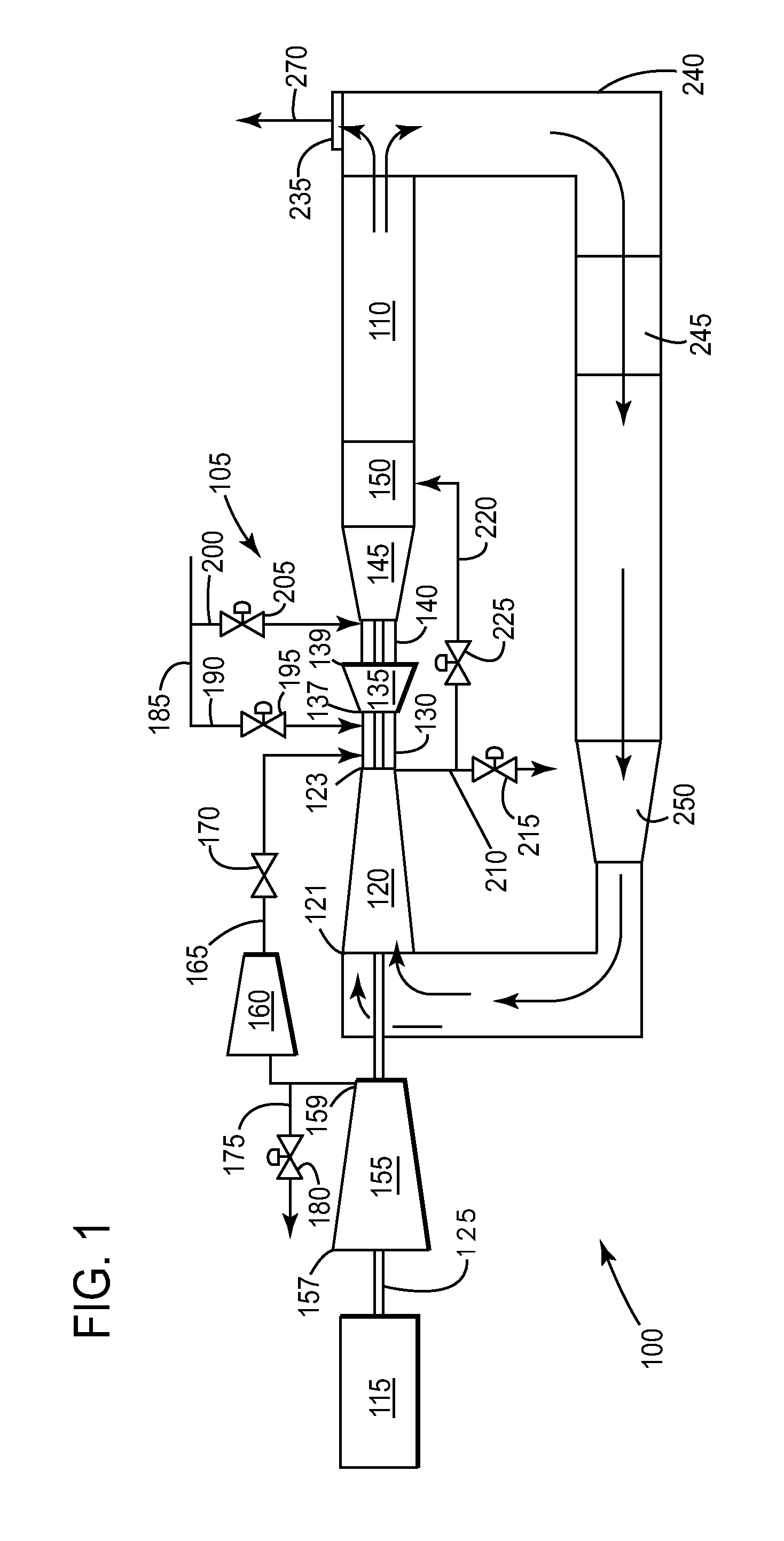
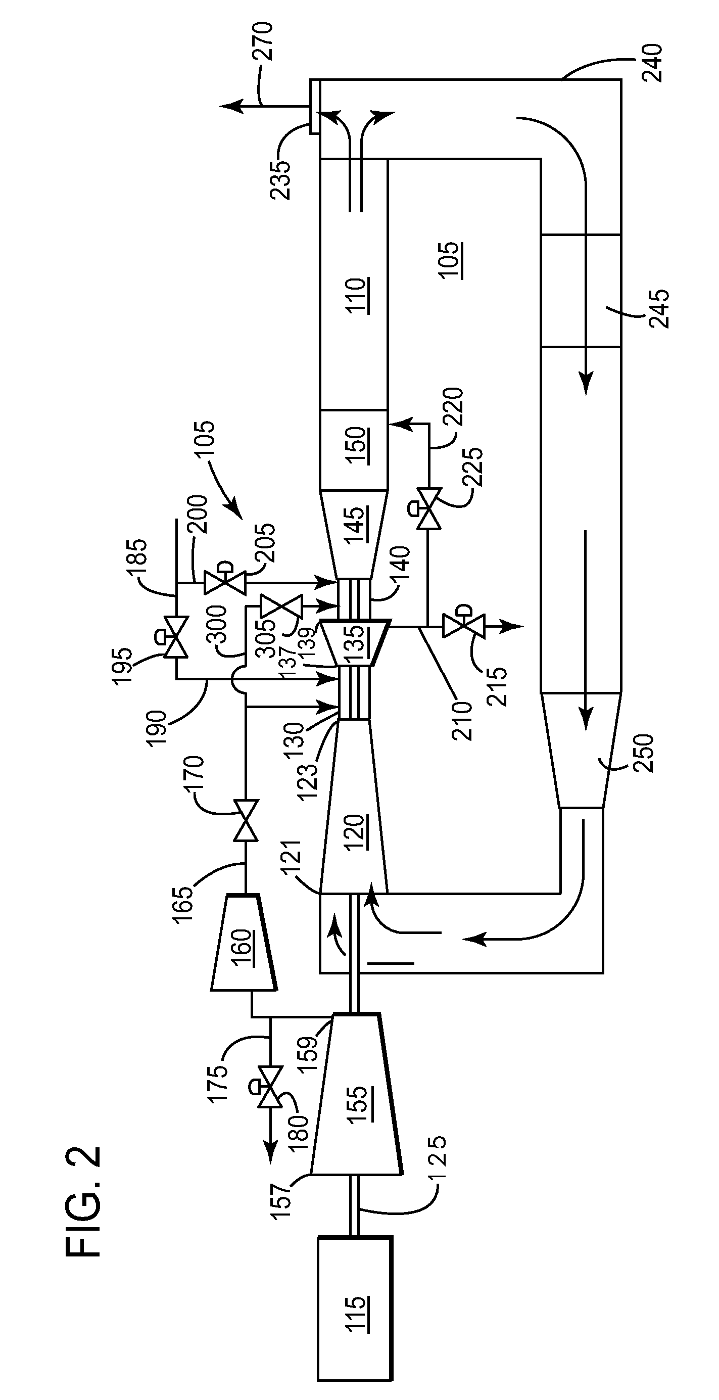
[0035]In use, embodiments of the present invention operate in conjunction with operations of the reheat gas turbine 105, as described in relation to FIGS. 1,2. In the present invention, the compressed oxidant may be passed through a cold side of the heat exchanger 310; and the extracted working fluid may be passed through an inlet of a hot side of the heat exchanger 310. Next, a portion of the compressed oxidant exiting the cold side of the heat exchanger 310 may be passed to a head end of the primary combustion system 130. Next, in a nearly simultaneous manner the remaining portion of the compressed oxidant exiting the cold side of the heat exchanger 310 may be passed to a head end of a secondary combustion system 140. Next, the working fluid exiting the hot side of the heat exchanger 310 may be passed through an outlet to a third-party process; which may include, but is not limited to, a carbon capture system.

second embodiment

[0036]In the present invention, the fuel may be passed through an inlet of a cold side of the heat exchanger 310; and the extracted working fluid may be passed through an inlet of the hot side of the heat exchanger 310. Next, a portion of the fuel exiting the cold side of the heat exchanger 310 may be passed through an outlet to a head end of the primary combustion system 130. Next, in a nearly simultaneous manner, the remaining portion of the fuel exiting the cold side of the heat exchanger 310 may be passed through an outlet to a head end of a secondary combustion system 140. Next, the working fluid exiting the hot side of the heat exchanger 310 may be passed through an outlet to a third-party process.

third embodiment

[0037]FIG. 5 is a simplified schematic of a reheat gas turbine 105 operating in a closed-cycle mode, illustrating the present invention. Here, a cold side of a heat exchanger 510 may be located in a flow stream between the ac_outlet 159 and the head end of the primary combustion system 130 and a head end of a secondary combustion system 140. The cold side of the heat exchanger 510 may also be located in a flow stream between the fuel supply 185 and the head end of the primary combustion system 130 and a head end of a secondary combustion system 140.


PUM


Abstract

Embodiments of the present invention provide a S-EGR process that yields an exhaust stream that includes a relatively high concentration of a desirable gas and is also substantially oxygen-free. This desirable gas includes, but is not limited to: Carbon Dioxide (CO2), Nitrogen (N2), or Argon.

Description

BACKGROUND OF THE INVENTION[0001]This application is related to [GE Docket 249101], [GE Docket 249104], [GE Docket 250883], [GE Docket 250884], [GE Docket 254241], [GE Docket 256159], [GE Docket 257411], and [GE Docket 258552] filed concurrently herewith, which are fully incorporated by reference herein and made a part hereof.[0002]The present application relates generally to a combined-cycle powerplant; and more particularly to a system and method for operating a turbomachine incorporated with stoichiometric exhaust gas recirculation (S-EGR).[0003]In an air-ingesting turbomachine, compressed air and fuel are mixed and combusted to produce a high energy fluid (hereinafter “working fluid”) that is directed to a turbine section. The working fluid interacts with turbine buckets to generate mechanical energy, which is transferred to a load. In particular, the turbine buckets rotate a shaft coupled to the load, such as an electrical generator. The shaft rotation induces current in a coil...

Claims


Application Information

Patent Timeline
Patent Type & Authority Applications(United States)
IPC IPC(8): F02C6/06
CPCF02C1/08F02C3/34Y02E20/16
Inventor BUTKIEWICZ, JEFFREY JOHNSIMPSON, STANLEY FRANKWICHMANN, LISA ANNE
Owner GENERAL ELECTRIC CO
Why Eureka
Try Eureka