Multibeam array of top emitting vcsel elements

a technology of vcsel elements and beam arrays, which is applied in the direction of lasers, semiconductor lasers, laser construction details, etc., can solve the problems of severe limitation of operational characteristics, extreme detrimental effects of combined heating effects on the properties and lifetime of photonic devices, and severe impairing of operational characteristics, so as to improve the illumination properties and capabilities of arrays

Active Publication Date: 2013-10-17
LUMENTUM OPERATIONS LLC
View PDF8 Cites 63 Cited by
  • Summary
  • Abstract
  • Description
  • Claims
  • Application Information

AI Technical Summary

Benefits of technology

[0002]The present disclosure is related to semiconductor devices and more particularly to method...

Problems solved by technology

VCSELs can be manufactured in arrays much more cost efficiently than EE arrays, but as the area of the VCSEL array grows, heat dissipation from all of the elements can severely limit operational characteristics.
If arrayed elements are not heat sunk properly, the combined heating effects will have extreme detrimental effects on the properties and lifetime of the photonic devices.
This in effect traps the heat being generated on or near the surface, thereby quickly “heating” such devices up to elevated temperatures, which begins to severely impair operational characteristics.
VCSEL devices can be fabricated with very high density which exasperates the problem.
Top emitting VCSEL designs are especially vulnerable to this problem.
As explained earlier, the thermal constraints of such arrays limit their output so the current technology is insufficient for many of the emerging applications.
This makes the VCSEL array emitters very useful for larger arrays, but the heating constraints of the top emit...

Method used


Image

  • Multibeam array of top emitting vcsel elements
  • Multibeam array of top emitting vcsel elements
  • Multibeam array of top emitting vcsel elements

Examples


Embodiment Construction

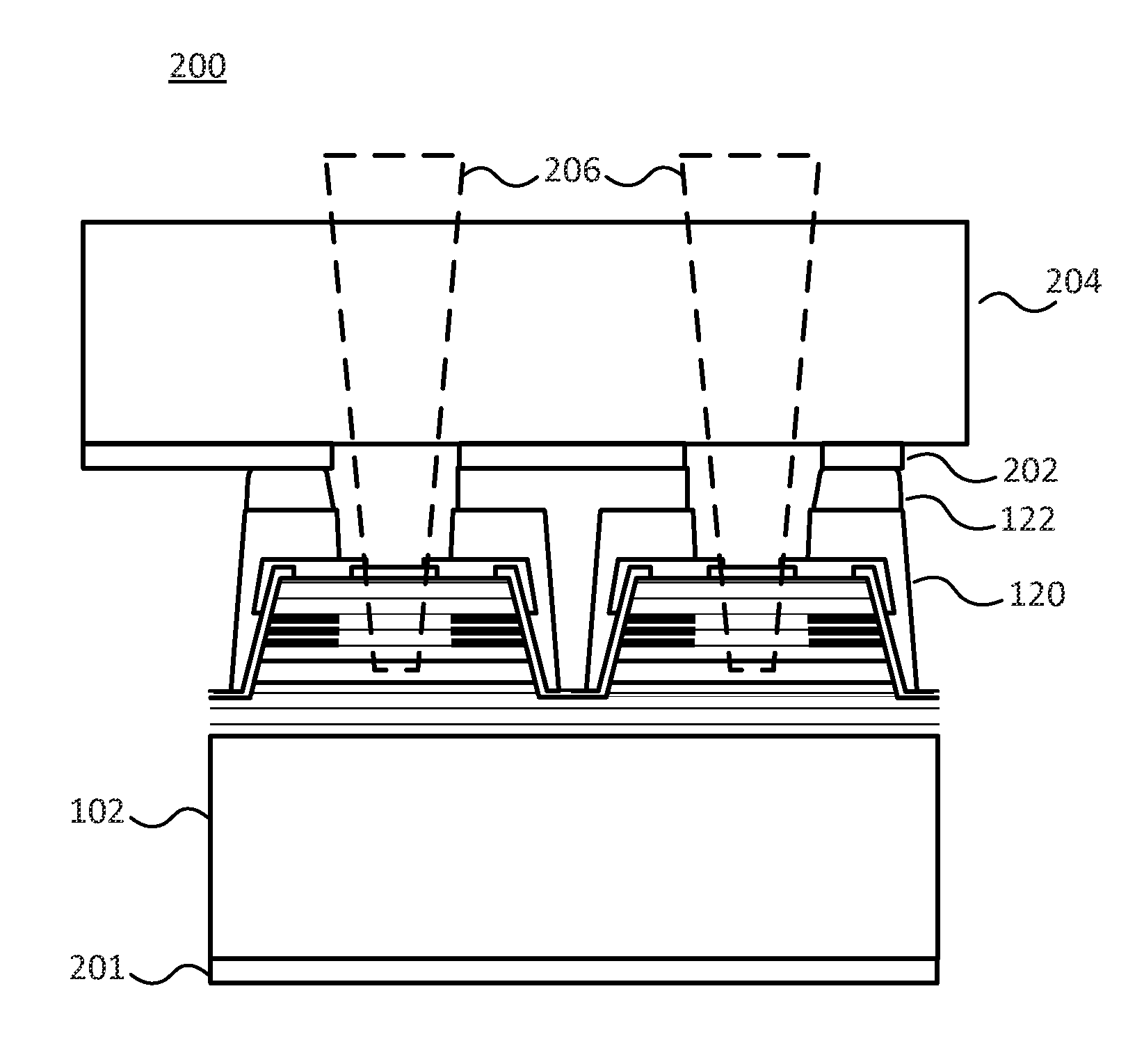
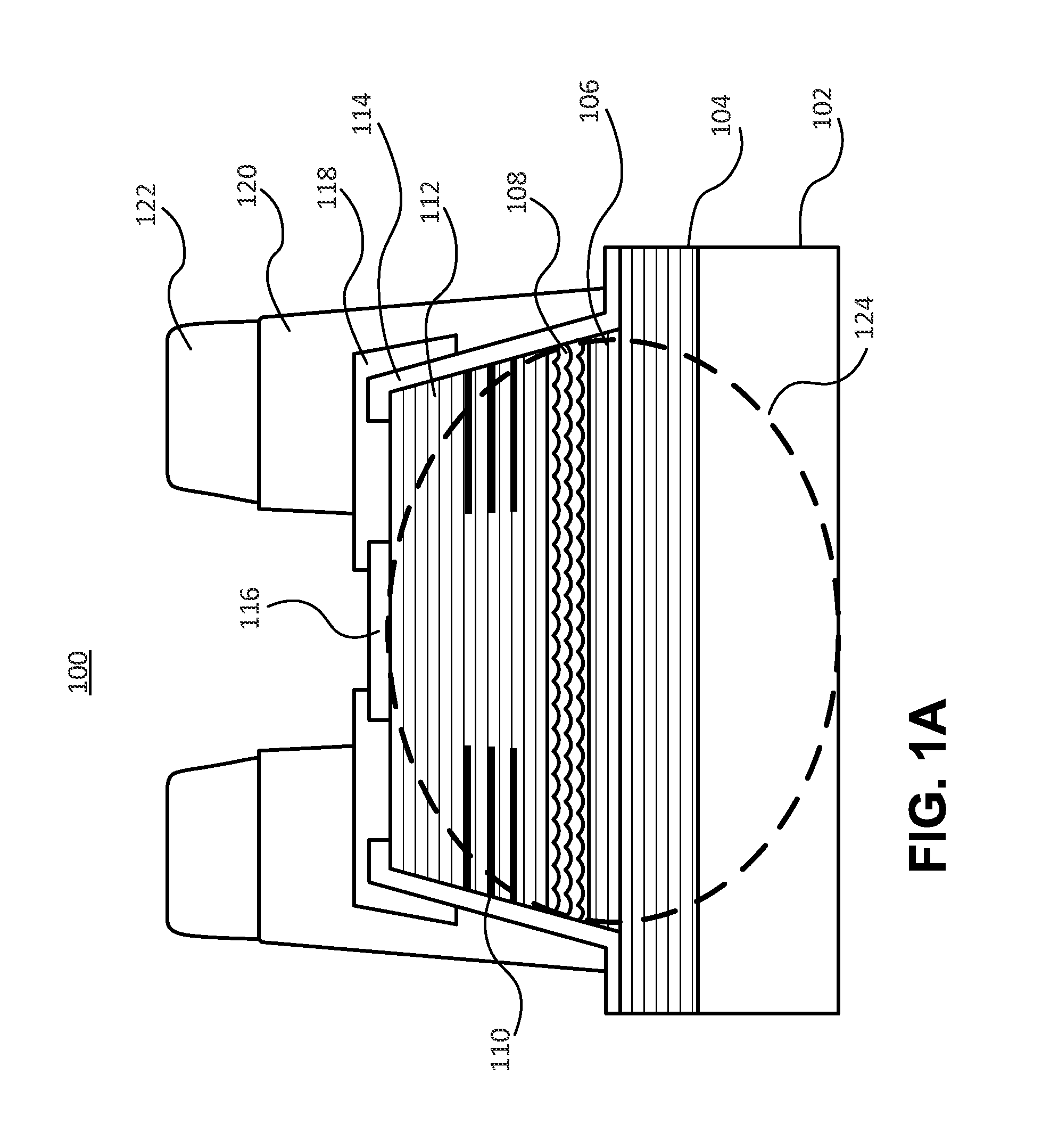
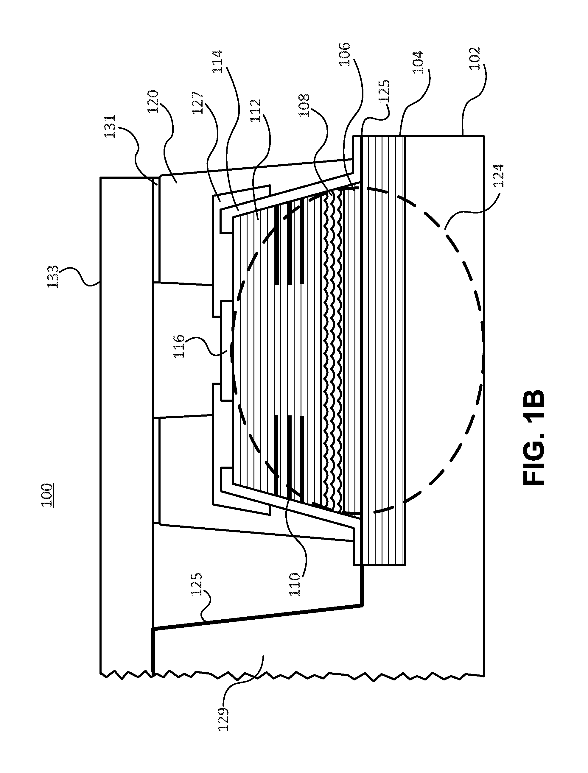
[0027]An embodiment is directed to a multibeam optoelectronic device, referred to as a VCSEL array device, which may have high power and may be thermally managed to improve performance from top emitting VCSEL arrays. The VCSEL array device may be a monolithic array of VCSELs comprised of two or more VCSELs and a thermal heat sink substrate positioned on the top of the devices but leaving windows or gaps over the aperture areas for light emission. Top emitting VCSEL arrays have much more difficulty removing heat from the multiple VCSEL devices than back emitting VCSEL arrays. If the heat is not removed from each device and transferred away quickly, the device's operational characteristics can degrade and the performance and reliability of the VCSEL devices will suffer. A dense array will lend itself to even more heat buildup reducing performance of the devices or burning up the devices like a fuse.

[0028]An embodiment may position the heat sinking apparatus at the most beneficial area...


PUM


Abstract

A top emitting VCSEL array may be coupled to a separate heat spreading superstrate that may be positioned above the apertures of the array and that may be able to transmit the emitted beams through the heat spreading superstrate. The VCSEL devices in the array may be controlled by an electrical connection to a pattern of conductive elements positioned in close contact with, but electrically isolated from, the heat spreading superstrate. The conductive elements may electrically control one or more of the VCSEL devices to enable sectional control of the light output. The elements may also be arraigned in a ground-signal-ground or coplanar waveguide configuration to improve the frequency response of the array.

Description

CROSS-REFERENCES TO RELATED APPLICATIONS[0001]This application claims benefit under 35 U.S.C. §119(e) of Provisional Patent Application Nos. 61 / 625,633, filed Apr. 17, 2012, and 61 / 675,282, filed Jul. 24, 2012, the contents of which are incorporated herein by reference in their entirety.TECHNICAL FIELD[0002]The present disclosure is related to semiconductor devices and more particularly to methods of improving the illumination properties and capabilities of arrays of top emitting photonic devices.BRIEF DESCRIPTION OF DISCLOSURE[0003]A top emitting VCSEL array is described that may be coupled to a separate heat spreading superstrate that may be positioned above the apertures of the array and that may be able to transmit the emitted beams through the heat spreading superstrate. The VCSEL devices in the array may be controlled by an electrical connection to a pattern of conductive elements positioned in close contact with, but electrically isolated from, the heat spreading superstrate....

Claims


Application Information

Patent Timeline
IPC IPC(8): H01S5/024H01S5/023
CPCH01S5/02476H01S5/02469H01S5/18313H01S5/18333H01S5/18391H01S5/423H01S2304/00H01S5/04254H01S2301/176H01S5/0234H01S5/0237H01S5/023H01S5/0233H01S5/0235H01S5/02345
Inventor JOSEPH, JOHN R.LEAR, KEVIN L.
Owner LUMENTUM OPERATIONS LLC
Why Eureka
Try Eureka