Coating apparatus and coating method

Inactive Publication Date: 2013-10-17
TOKYO OHKA KOGYO CO LTD
View PDF7 Cites 33 Cited by
  • Summary
  • Abstract
  • Description
  • Claims
  • Application Information

AI Technical Summary

Benefits of technology

[0065]In this embodiment, by virtue of the baking step in which the liquid material is baked, even in the case where cracks and the like are formed on a peripheral por

Problems solved by technology

In such a method of forming the light absorbing layer, the following problems arise.
For example, the coating film formed on the substrate is likely to have cracks and the like form

Method used


Image

  • Coating apparatus and coating method
  • Coating apparatus and coating method
  • Coating apparatus and coating method

Examples


Example

[0096]Hereinafter, one embodiment of the present invention will be described with reference to the accompanying drawings.

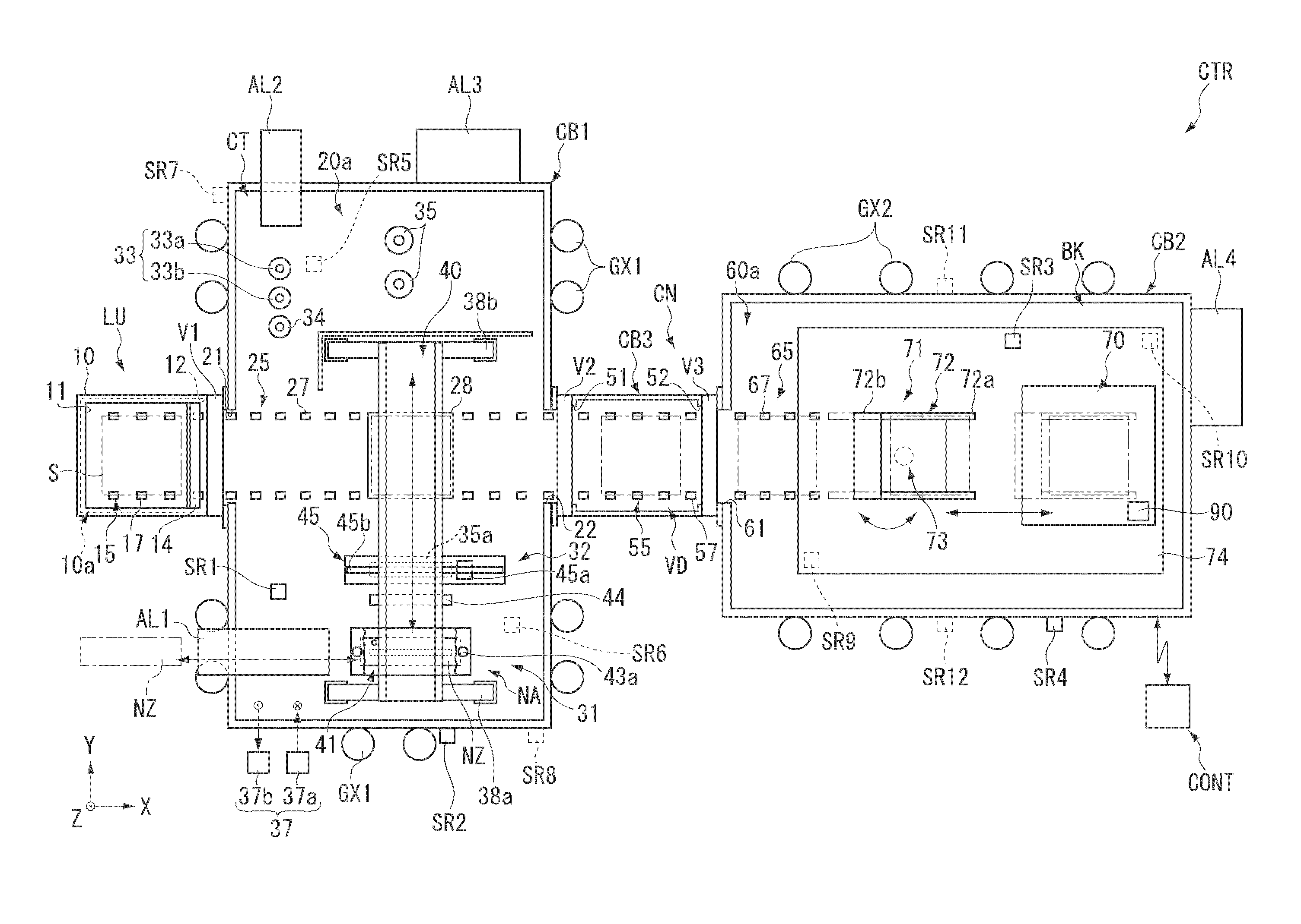
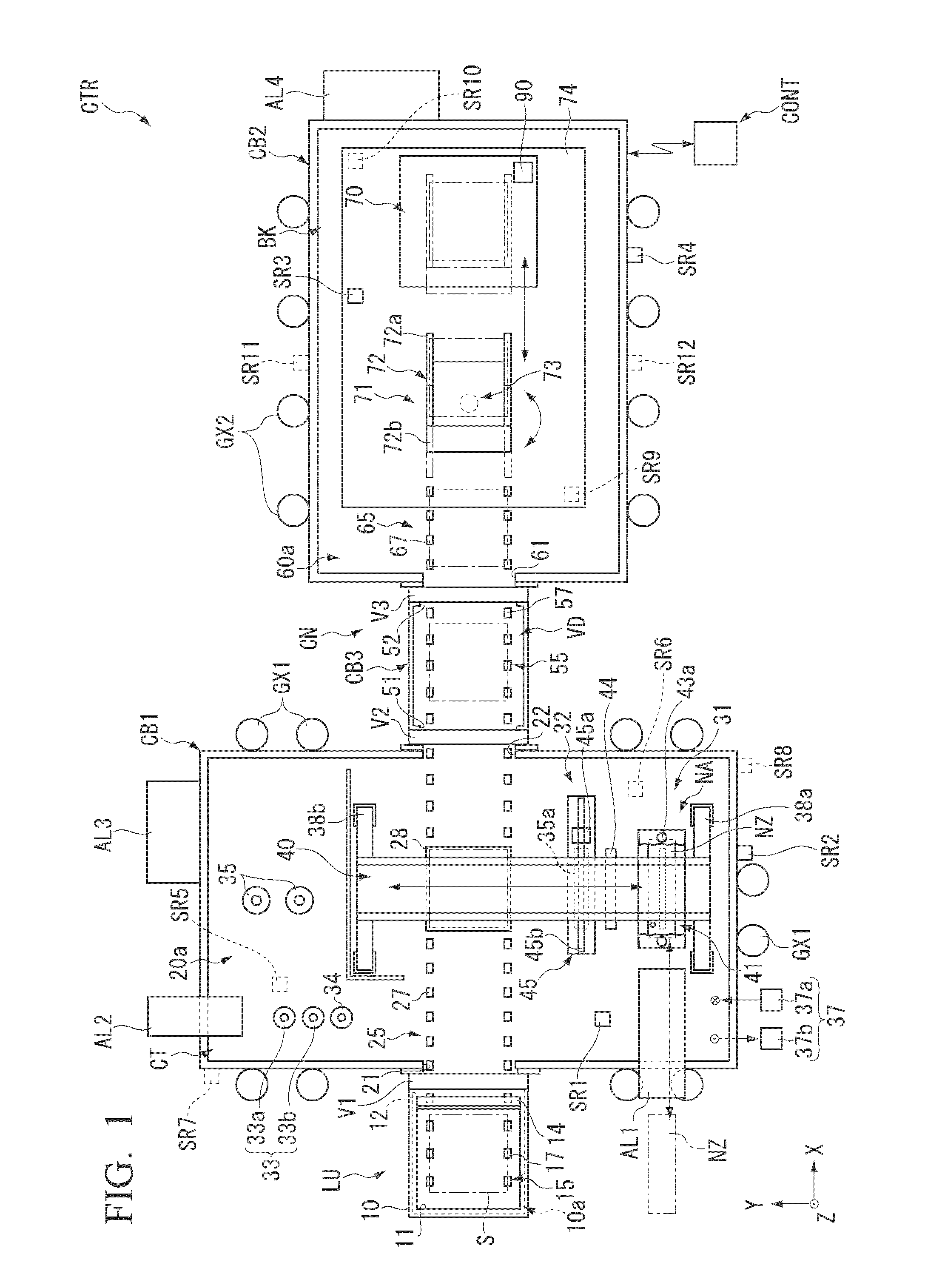
[0097]FIG. 1 is a schematic diagram showing a configuration of a coating apparatus CTR according to one embodiment of the present invention.

[0098]As shown in FIG. 1, the coating apparatus CTR is an apparatus which applies a liquid material to a substrate S. The coating apparatus CTR includes a substrate loading / unloading part LU, a first chamber CB1, a second chamber CB2, a connection part CN and a control part CONT. The first chamber CB1 has a coating part CT. The second chamber CB2 has a baking part BK. The connection part CN has a vacuum drying part VD.

[0099]The coating apparatus CTR is used, for example, by being disposed on a floor FL in a factory. The coating apparatus may have a configuration in which the coating apparatus is accommodated in one room, or a configuration in which the coating apparatus is divisionally accommodated in a plurality of rooms. In ...


PUM


Abstract

A coating apparatus including a coating part which coats a liquid material containing a metal on a substrate, a coating-film forming part which subjects the liquid material coated on the substrate to a predetermined treatment to form a coating film, and a removing part which removes a peripheral portion of the coating material formed along the outer periphery of the substrate.

Description

[0001]This application claims priority to U.S. Provisional Application No. 61 / 625,477 filed on Apr. 17, 2012, the content of which is incorporated herein by reference.FIELD OF THE INVENTION[0002]The present invention relates to a coating apparatus and a coating method.DESCRIPTION OF THE RELATED ART[0003]A CIGS solar cell or a CZTS solar cell formed by semiconductor materials including a metal such as Cu, Ge, Sn, Pb, Sb, Bi, Ga, In, Ti, Zn, and a combination thereof, and a chalcogen element such as S, Se, Te, and a combination thereof has been attracting attention as a solar cell having high conversion efficiency (for example, see Patent Documents 1 to 3).[0004]For example, a CIGS solar cell has a structure in which a film including four types of semiconductor materials, namely, Cu, In, Ga, and Se is used as a light absorbing layer (photoelectric conversion layer). Further, for example, a CZTS solar cell has a structure in which a film including four types of semiconductor materials,...

Claims


Application Information

Patent Timeline
IPC IPC(8): B05D3/12B05D3/04B05D3/06B05D3/02
CPCB05D3/12B05D3/02B05D3/04B05D3/06Y02E10/541H01L31/0322H01L31/0326H01L31/18C30B9/10H01L21/6715C30B1/02C30B7/06C30B29/46
Inventor MIYAMOTO, HIDENORI
Owner TOKYO OHKA KOGYO CO LTD
Why Eureka
Try Eureka