Method for Adjusting a DC Voltage Intermediate-Circuit Voltage

a technology of intermediate circuit voltage and dc voltage, which is applied in the direction of secondary cell servicing/maintenance, motor/generator/converter stopper, dynamo-electric converter control, etc., can solve the problems of large and heavy components, not only expensive, but also large and heavy, and achieve the effect of reducing the switching speed of the coupling unit of the battery module and charging in a shorter period of tim

Active Publication Date: 2013-10-24
ROBERT BOSCH GMBH +1
View PDF1 Cites 9 Cited by
  • Summary
  • Abstract
  • Description
  • Claims
  • Application Information

AI Technical Summary

Benefits of technology

[0014]The method of the invention provides the advantage that the output voltage of the battery is switched rapidly and in a controlled manner between the first and the second selected output voltage, as a consequence of which a time-averaged adjustable charging current for the DC voltage intermediate circuit is provided. Since the charging current is adjusted to a desired value by selecting suitable first and second variable periods of time and consequently said charging current can also be limited, the charging switch 120 and the charging resistor 121 of the battery systems of the prior art can be omitted as a result of which costs, volume and weight of a battery system that functions according to the method in accordance with the invention can be correspondingly reduced. As the battery is embodied to provide different output voltages by activating or deactivating the individual series-connected battery modules, it is possible in order to adjust the voltage of the DC voltage intermediate circuit to select the two output voltages of the battery that are the closest in value to the instantaneous value of the voltage and to switch between said two output voltages with the appropriate first and second variable periods of time in order to influence the voltage of the DC voltage intermediate circuit as desired. As a result of selecting the two closest output voltages of the battery, the ripple content of the charging current is reduced to a minimum which owing to the inevitably present inductances and capacities can only occur at a limited rate of change of the output voltage of the battery. The switching speed of the coupling units of the battery modules can also be reduced accordingly.
[0015]The method of the invention has in addition the advantage that the DC voltage intermediate circuit can be charged in a shorter period of time. In a battery system having the battery that is illustrated in FIG. 2 and that comprises a charging and disconnecting device 116, the DC voltage intermediate circuit is charged with a characteristic that corresponds to an exponential function with negative exponents until the switch 118 closes. This means that the maximum charging current flows at the commencement of the charging process so that the voltage of the DC voltage intermediate circuit approaches the value of the output voltage of the battery in an asymptotic manner; said maximum charging current does, however, continue to reduce as the process of charging the DC voltage intermediate circuit proceeds. However, the voltage of the DC voltage intermediate circuit can increase in a linear manner in accordance with the method of the invention and thus the capacity of the DC voltage intermediate circuit can be charged during the entire charging period of time to an averaged constant current that is at least a similar value to that of the initial charging current in a battery system having a charging resistor 121. As a consequence, the first desired operating voltage is achieved correspondingly more rapidly.
[0019]The method can comprise an additional step of measuring a prevailing charging current. As a consequence thereof, a closed loop control method that is being used can also take into consideration the prevailing charging current or it can implement safety mechanisms to provide protection from inadmissibly high charging currents.
[0024]It is particularly preferred in this case that the battery cells of the battery modules are lithium-ion battery cells. Lithium-ion battery cells have the advantages of a high cell voltage and high energy content in a given volume.

Problems solved by technology

Otherwise, as a result of the high DC voltage of the battery cells that are connected in series, there is a considerable potential risk for maintenance personnel or the like.
Said components are not only expensive but they are also large and heavy which is particularly troublesome when used in mobile applications such as electric motor vehicles.

Method used


Image

  • Method for Adjusting a DC Voltage Intermediate-Circuit Voltage
  • Method for Adjusting a DC Voltage Intermediate-Circuit Voltage
  • Method for Adjusting a DC Voltage Intermediate-Circuit Voltage

Examples


first embodiment

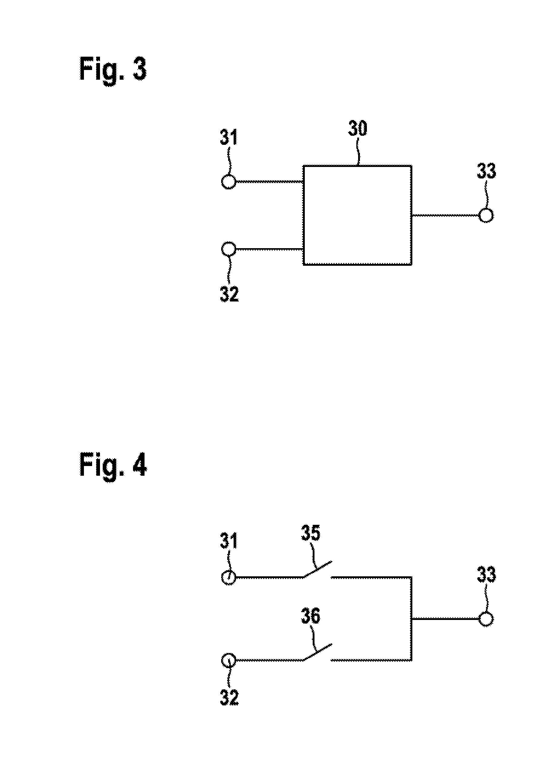
[0040]FIG. 3 illustrates a coupling unit 30 for use in a battery with which the method in accordance with the invention can be performed. The coupling unit 30 comprises two inputs 31 and 32 and also an output 33 and is embodied to connect one of the inputs 31 or 32 to the output 33 and to disconnect the other one.

[0041]FIG. 4 illustrates a possible implementation of the first embodiment of the coupling unit 30 with regard to the switching technology, wherein a first and a second switch 35 and 36 respectively are provided. Each of the switches is connected between one of the inputs 31 and 32 respectively and the output 33. This embodiment provides the advantage that it is also possible to disconnect the two inputs 31, 32 from the output 33, so that the output 33 is a high impedance output, which can be useful, for example, in the case of making a repair or carrying out maintenance. In addition, the switches 35, 36 can be embodied simply as semi-conductor switches such as MOSFETs or I...

second embodiment

[0043]FIG. 7 illustrates a coupling unit 50 for use in a battery with which the method in accordance with the invention can be performed. The coupling unit 50 comprises two inputs 51 and 52 and also two outputs 53 and 54. Said coupling unit is embodied to connect either the first input 51 to the first output 53 and also to connect the second input 52 to the second output 54 (and to disconnect the first output 53 from the second output 54) or else to connect the first output 53 to the second output 54 (and in so doing to disconnect the inputs 51 and 52). In the case of particular embodiments of the coupling unit, said coupling unit can also be embodied to disconnect the two inputs 51, 52 from the outputs 53, 54 and also to disconnect the first output 53 from the second output 54. However, it is not provided that it can also connect the first input 51 to the second input 52.

[0044]FIG. 8 illustrates a possible implementation of the second embodiment of the coupling unit 50 with regard ...


PUM


Abstract

A method is disclosed for adjusting a voltage of a DC-voltage intermediate circuit in a battery system having a battery and a drive system. The battery is configured to output one selectable output voltage from n+1 different output voltages. In a first step of the method, an actual value of the voltage of the DC-voltage intermediate circuit is determined, and is then compared with the various output voltages of the battery. A first selected output voltage of the battery, which is the highest voltage of those output voltages of the battery which are less than the actual value of the voltage of the DC-voltage intermediate circuit, and a second selected output voltage of the battery, which is the lowest voltage of those output voltages of the battery which are higher than the actual value of the voltage of the DC-voltage intermediate circuit, are then selected.

Description

[0001]The present invention relates to a method for adjusting a DC voltage intermediate circuit voltage and to a battery and a battery system having a DC voltage intermediate circuit that are embodied to perform the method.PRIOR ART [0002]It has become apparent that in future, both in the case of stationary applications and also in the case of vehicles such as hybrid vehicles and electric vehicles, battery systems will be used ever more frequently. In order to be able to meet particular requirements for a respective application voltage and the power that can be made available, a high number of battery cells are connected in series. Since it is necessary for the current that is provided by a battery of this type to flow through all the battery cells and a battery cell can only carry a limited amount of current, battery cells are in addition often connected in parallel in order to increase the maximum current. This can be achieved either by providing a plurality of battery cells withi...

Claims


Application Information

Patent Timeline
Patent Type & Authority Applications(United States)
IPC IPC(8): H02P6/08H02M3/10
CPCH02P6/08H02M3/10H01M10/441H01M10/482H01M16/00H02J7/0013H02M1/36Y02T10/92B60L58/22Y02T10/70Y02E60/10H02J7/00H01M10/44
Inventor FINK, HOLGER
Owner ROBERT BOSCH GMBH
Why Eureka
Try Eureka