Route guidance system and method

a technology of route guidance and route, applied in the direction of synchronisation arrangement, broadcast service distribution, instruments, etc., can solve the problems of system in widespread use, widespread use not being implemented or planned, and vehicle accident cost in the us is approximately $300 billion per year. , to achieve the effect of efficient encoding of vehicle size and weigh

Active Publication Date: 2013-10-24
SAMSUNG ELECTRONICS CO LTD
View PDF5 Cites 118 Cited by
  • Summary
  • Abstract
  • Description
  • Claims
  • Application Information

AI Technical Summary

Benefits of technology

[0030]Core data messages are transmitted using the most reliable encoding supported by 802.11p, which is a 3 mbit / sec, OFDM, BPSK encoding. Non core-data messages may be transmitted with an encoding for a higher data rate, such as 6 mbit / sec or 12 mbit / sec. This allows more data to be placed in a message that still occupies only a single time slot.
[0117]A unique benefit of such above methods is the elimination of the need for users of a V2V transponder, device, software, app or system to subscribe to mapping service or other for-charge service.

Problems solved by technology

Thus, the cost of vehicle accidents in the US is approximately $300 billion per year.
However, such systems are not in widespread use, nor is widespread use being implemented or planned.
These systems as proposed and developed suffer from serious weaknesses.
One weakness is unnecessary complexity.
This complexity hinders development speed and adds cost, which further delays deployment.
Another, even more serious weakness, is that the proposed systems will not in fact be effective at significantly reducing accidents for many years.
Even reaching a 25% installed density of V2V systems will take many years, assuming current trends on new vehicle purchases.
Thus, with the V2V systems currently proposed, there will not be sufficient motivation by either buyers to purchase optional V2V systems, or for the government to mandate required V2V systems.
This calculated low effectiveness of proposed systems understates the problem.
In fact, a higher proportion of accidents are caused by older vehicles than new vehicles.
Also, for early buyers, the effectiveness is even less than the eventual 3%.
Thus, equipping only new vehicles is even less effective that the uniform distribution assumed in the above calculations.
Another serious weakness of V2V systems as proposed is the use of an inappropriate, non-deterministic basis for message transmission.
Yet another serious weakness of V2V systems as proposed is lack of a simple, usable priority system that is integrated with bandwidth allocation.
Yet another serious weakness of V2V systems as proposed is lack of clear distinction between emergency vehicle messages and non-emergency vehicle messages.
Yet another serious weakness of V2V systems as proposed is lack of clear bandwidth allocation rules separating safety-related messages from non-safety related messages.
Yet another serious weakness of V2V systems as proposed is lack of dynamic ability to calibrate and reduce location errors between different vehicles.
Yet another serious weakness of V2V systems as proposed is the lack of ability to retransmit messages in a relay.
Yet another serious weakness of V2V systems as proposed is the lack of ability to send “courtesy” messages.
Yet another serious weakness of V2V systems as proposed is a lack of ability to practically include pedestrians and bicycles in the system.
Yet another serious weakness of V2V systems as proposed is a lack of ability to take advantage of widely popular personal, mobile electronic devices to increase the installed penetration rate.
Yet another serious weakness of V2V systems as proposed is a method to limit transmission power; or a method to limit range.
Yet another serious weakness of V2V systems as proposed is lack of a complete application layer protocol, such as message formats and meanings.
Without this specification there is no compatibility between different manufacturers or implementations.
Yet another serious weakness of V2V systems as proposed is lack of roadway lane information.

Method used


Image

  • Route guidance system and method
  • Route guidance system and method
  • Route guidance system and method

Examples


Embodiment Construction

[0119]

Table of ContentsConcept and Definitions16Proxying19Physical Layer27Vehicle Identification49Power Management52Time Slots61Message Classes68Message Formats68Message Types85Risk Determination94Location History100Time Slot Assignment and Message Collisions106Position Determination106Lane Maps114Vehicle Elevation125Forwarding127Hacking and Security132Recording and Encryption134Traffic Signal Optimization137Parking, Courtesy Messages and Gateways146

BRIEF DESCRIPTION OF THE DRAWINGS

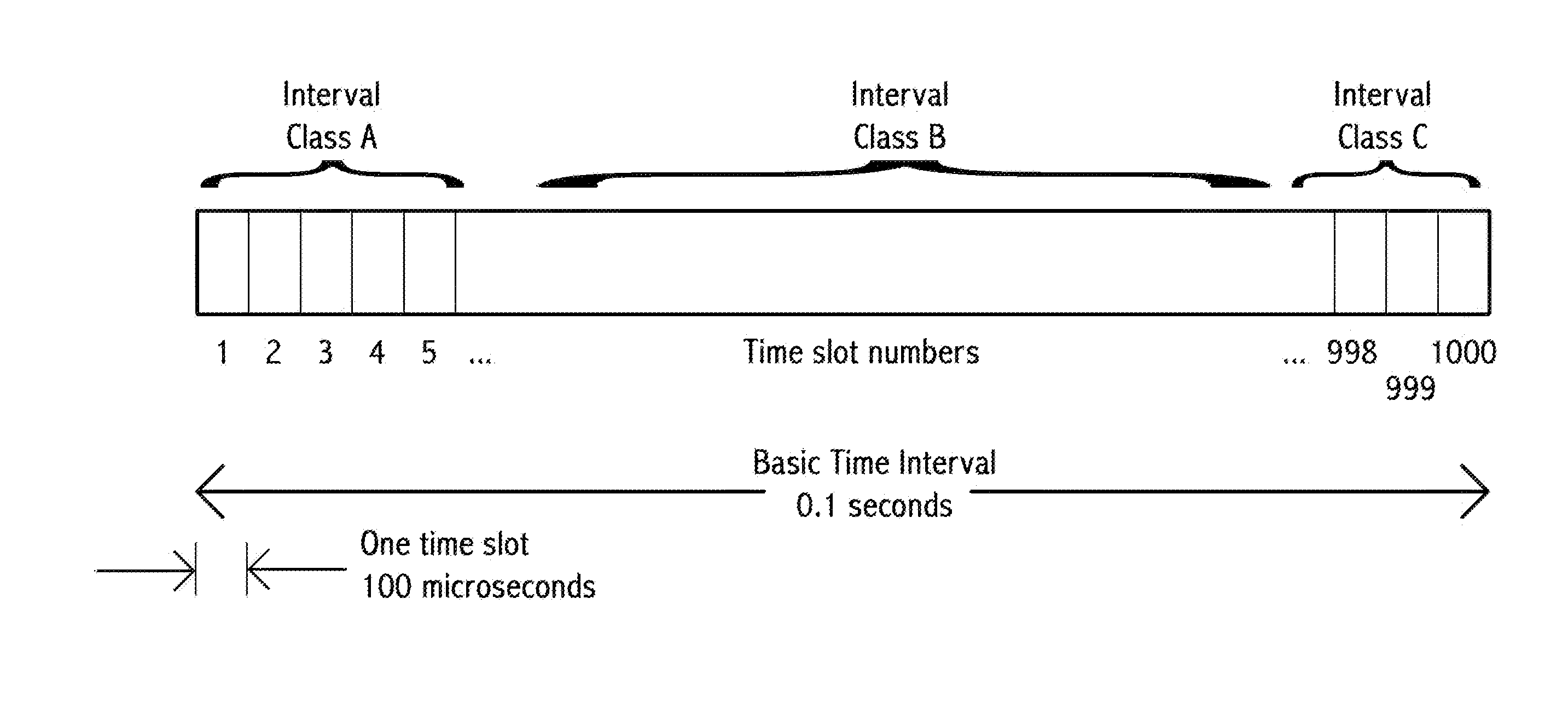
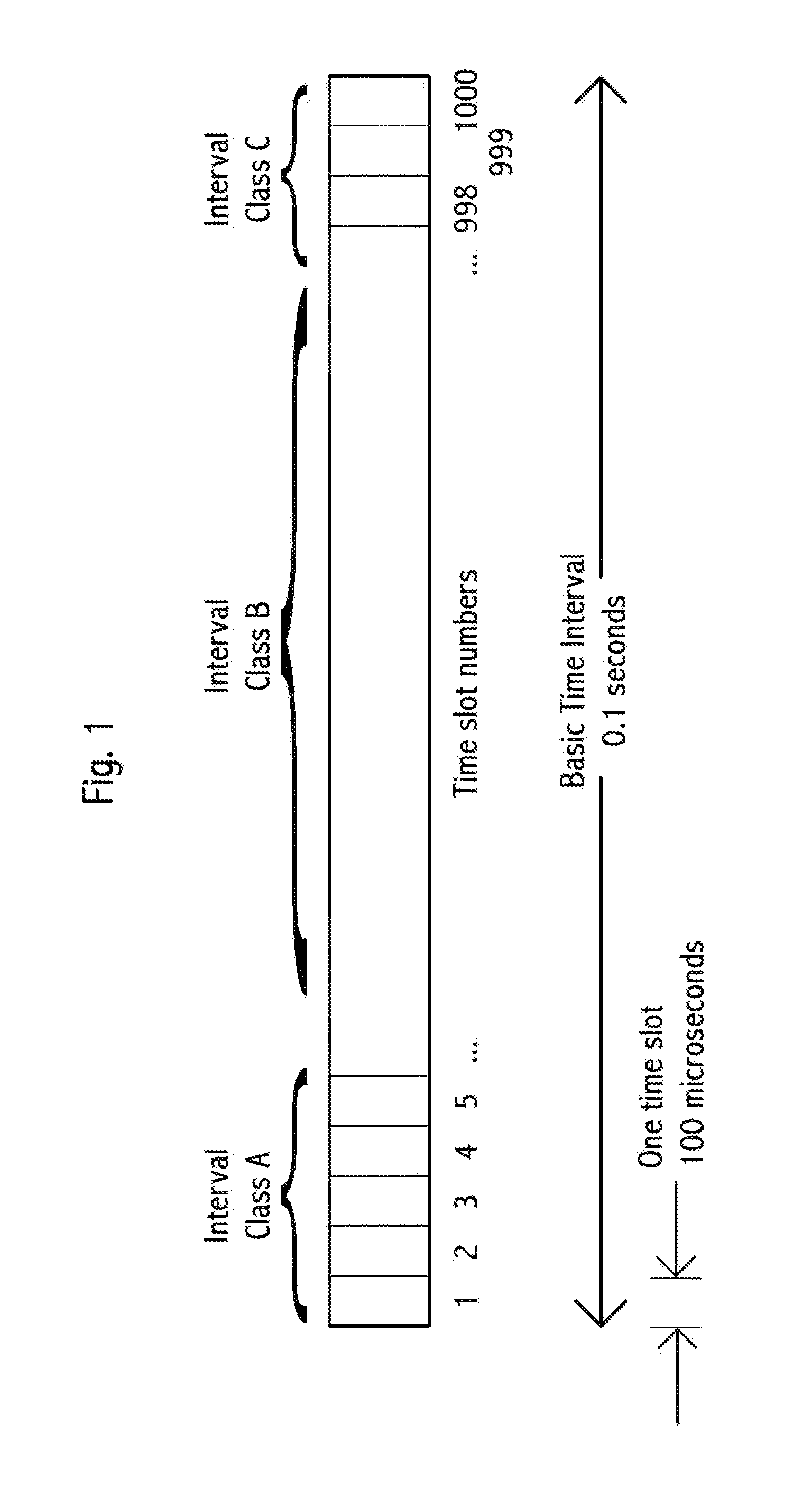
[0120]FIG. 1 shows a basic time interval of 0.1 s with 1000 numbered time slots, each 100 μs.

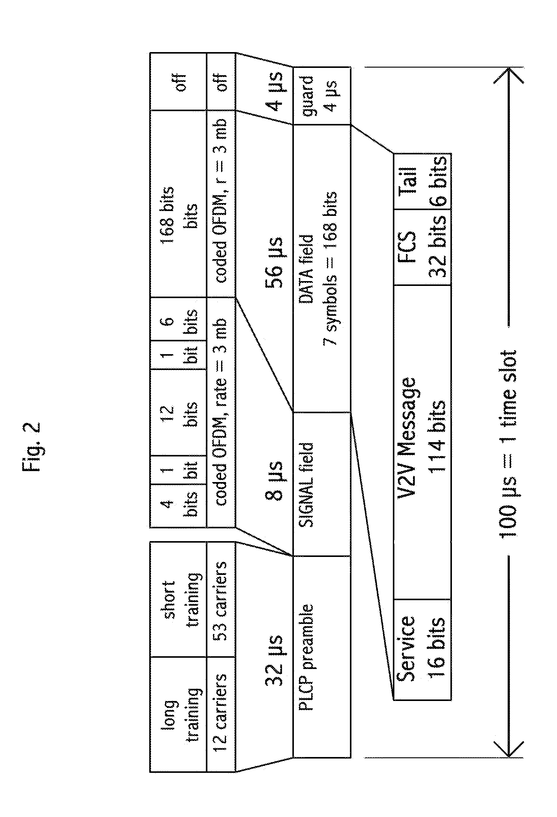
[0121]FIG. 2 shows a single 100 μs message frame in IEEE 802.11p format, with a 3 mbit / s modulation, comprising SIGNAL, SERVICE, FCS, and Tail fields, with 114 bits available for a V2V message.

[0122]FIG. 3 shows a single 100 μs message frame in IEEE 802.11p format, with a 6 mbit / s modulation, comprising SIGNAL, SERVICE, FCS, and Tail fields, with 282 bits available for a V2V message.

[0123]FIG. 4 shows thee exempla...


PUM


Abstract

Device, system and method, in a vehicle communication system, of providing guidance, route and safety information to a driver. Embodiments use the observation and storage of signal light timing information to make recommendations. Embodiments include computation of future times of signal light changes. Embodiments use information relating to the number of vehicles, location of vehicles, and speed of vehicles in a plurality of lanes approaching a signal to recommend lane changes to a driver. Embodiments include receiving timing information wirelessly about signal timing. Embodiments include using historical information to compute a risk value for a location and then generating a recommendation to a driver responsive to that risk value. Embodiments include using speed of travel on route options to compute an expected travel time, and then generating a recommendation to a driver responsive to those computed travel times.

Description

[0001]This application claims priority to the U.S. Patent Application No 61 / 637,588, dated 24 Apr. 2012.BACKGROUND OF THE INVENTION[0002]Four people are killed in motor vehicle accidents in the US every hour. Based on 2007 information from the National Association of Commissioners of Insurance and 2008 information from the United States Department of Transportation (DOT), the cost of vehicle insurance in the US in 2008 was $201 billion.[0003]Consumer Reports magazine in 2012 reported an additional $99 billion dollars in medical costs and lost time due to vehicle accidents every year in the US.[0004]Thus, the cost of vehicle accidents in the US is approximately $300 billion per year. This is approximately $1000 for every US resident every year.[0005]Various technology-based methods have been proposed to reduce the number of vehicle accidents. The basis of some of these methods is wireless transmission by a sending vehicle of its position and speed, then the computation by a receiving...

Claims


Application Information

Patent Timeline
Patent Type & Authority Applications(United States)
IPC IPC(8): G08G1/16G01C21/28G01C21/34H04W4/46H04W4/48
CPCH04W64/006G08G1/161H04W4/06H04W56/0035H04W76/14H04W76/40H04W4/027G01C21/3822H04W4/48H04W4/46B60W2556/50H04W72/30G08G9/02G08G1/09G08G1/142B60R25/33B60R2325/205G01C21/26G01S5/0027G08G1/20G01C21/3658G08G1/096791G08G1/0969G08G1/163G08G1/166G08G1/167B60W10/06B60W10/18B60W10/20B60W50/14G08G1/16H04J3/1694H04L5/0091H04W72/0446H04W74/0816
Inventor RUBIN, KIM TBETTS-LACROIX, JONATHAN N.
Owner SAMSUNG ELECTRONICS CO LTD
Why Eureka
Try Eureka