

Micromechanical component and method for manufacturing a micromechanical component
a micromechanical component and micromechanical technology, applied in the direction of fluid speed measurement, acceleration measurement using interia forces, instruments, etc., can solve the problems of micromechanical components no longer being usable subsequently, local liquefaction of eutectic, spreading uncontrollably, etc., to achieve the effect of preventing the penetration
- Summary
- Abstract
- Description
- Claims
- Application Information
AI Technical Summary
Benefits of technology
Problems solved by technology
Method used
Image

Examples
Embodiment Construction
[0022]The same parts are always provided with the same reference numerals in the various figures and are each therefore generally cited or mentioned only once.
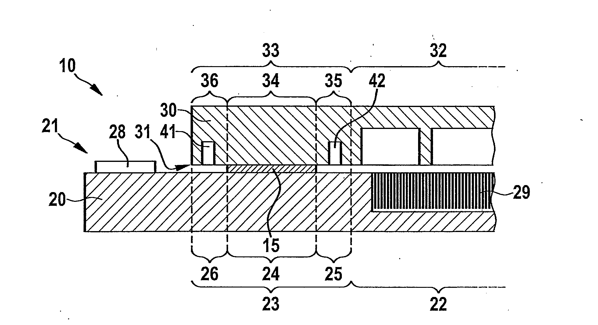
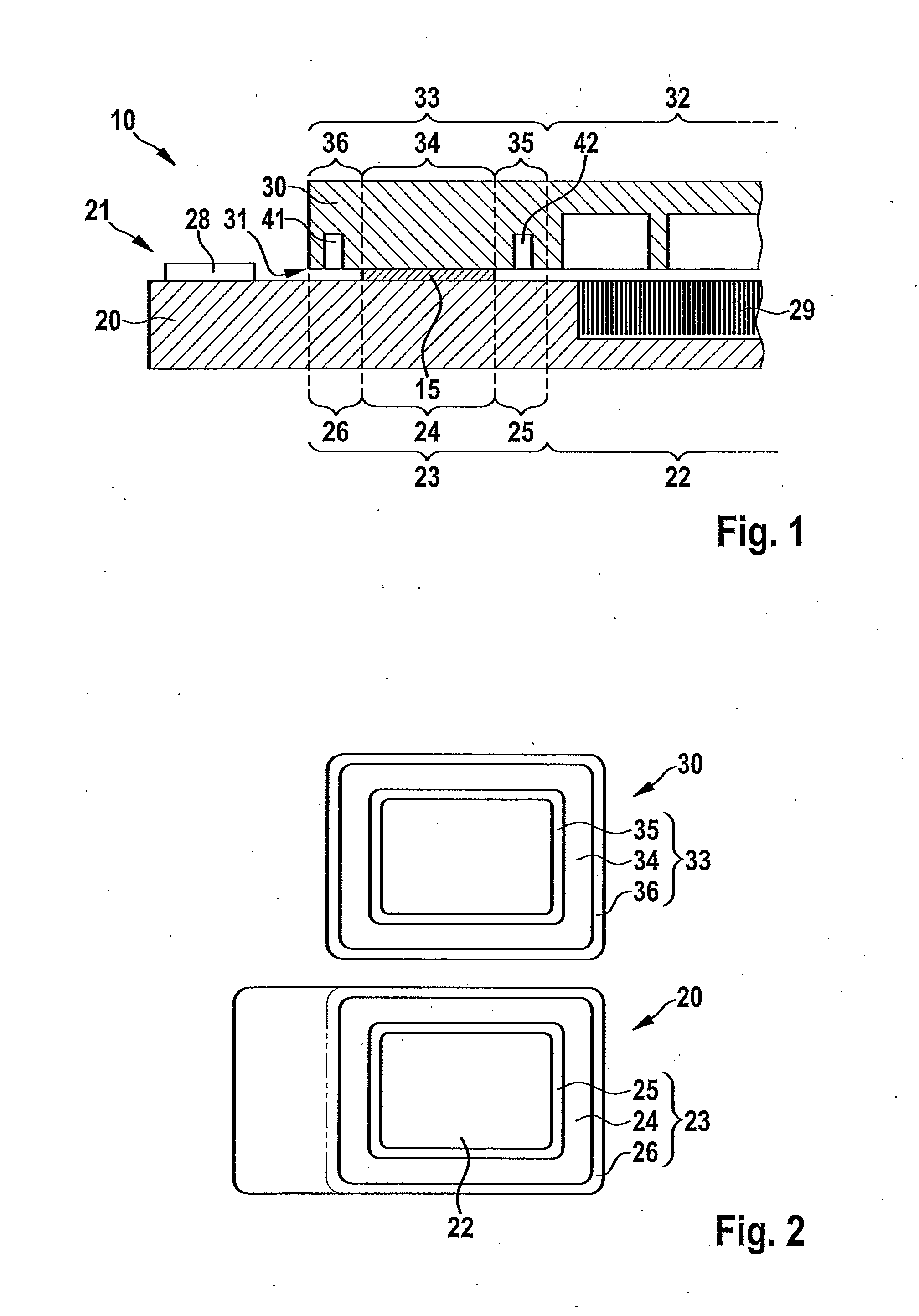
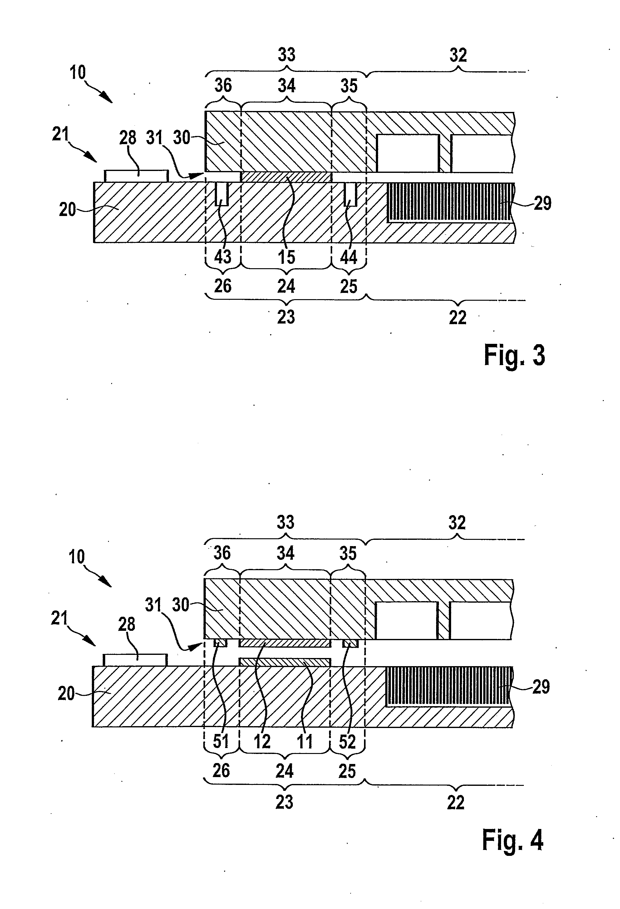
[0023]FIGS. 1, 3, 4, 5, 6 and 7 each show a part of a micromechanical component 10 according to the present invention in a schematic sectional diagram, micromechanical component 10 having a carrier substrate 20 and a cap substrate 30. Carrier substrate 20 has a first connecting side 21, and cap substrate 30 has a second connecting side 31, carrier substrate 20 and cap substrate 30 being joined together with their corresponding connecting sides 21 and 31 facing one another, a eutectic bond connection (or a solder connection) being provided in the edge areas of carrier substrate 20 and cap substrate 30 according to the present invention. Carrier substrate 20 has a first structured area 22 and a first edge area 23, first edge area 23 at any rate having a first connecting area 24 and a first bordering area 25 according to the pres...
PUM
| Property | Measurement | Unit |
|---|---|---|
| thickness | aaaaa | aaaaa |
| melting points | aaaaa | aaaaa |
| melting points | aaaaa | aaaaa |
Abstract
Description
Claims
Application Information