Manufacturing method of top plate of plasma processing apparatus

a plasma processing apparatus and manufacturing method technology, applied in the direction of paper/cardboard containers, containers, synthetic resin layered products, etc., can solve the problems of uneven etching rate or film thickness, abnormal electric discharge of plasma in the gas passage,

Inactive Publication Date: 2013-11-07
TOKYO ELECTRON LTD
View PDF18 Cites 402 Cited by
  • Summary
  • Abstract
  • Description
  • Claims
  • Application Information

AI Technical Summary

Benefits of technology

[0013]The present invention has been made focusing on the issues described above to effectively resolve these. The objective of the present invention is to prevent a plasma abnormal electric discharge in a plasma processing apparatus in which an electromagnetic wave for generating a plasma and a gas are introduced through a top plate of a processing container or a shower head.
[0020]In this way, by providing the discharge prevention member consisting of a dielectric body having a permeability in each ejection hole provided to the top plate of the processing container, the plasma abnormal electric discharge can be prevented while maintaining the introduction of the gas into the processing container through the gas ejection hole.
[0022]In a case when a gas channel is provided to the top plate for guiding the gas supplied from the gas supplying system to the gas ejection holes, it is preferable to also provide the discharge prevention member to this gas channel. This prevents an abnormal plasma electric discharge in the gas channel while maintaining the circulation of the gas in the gas channel.

Problems solved by technology

As a result of this, there have been cases of an uneven etching rate or film thickness by the plasma processing a wafer face.
However, in this case, the electric field strength inside the gas channel formed in the center of the top plate is high, and the plasma in the processing space easily intrudes into the gas passage from the front end opening of the gas passage, thus there are cases where an abnormal electric discharge occurs in the gas passage.
However, this configuration can not be adopted because the electric field strength inside the gas channel is high, and the plasma in the processing space easily intrudes into the gas passage from the front end opening of the gas passage in this case as well, thereby the plasma abnormal electric discharge occurs.

Method used


Image

  • Manufacturing method of top plate of plasma processing apparatus
  • Manufacturing method of top plate of plasma processing apparatus
  • Manufacturing method of top plate of plasma processing apparatus

Examples


first embodiment

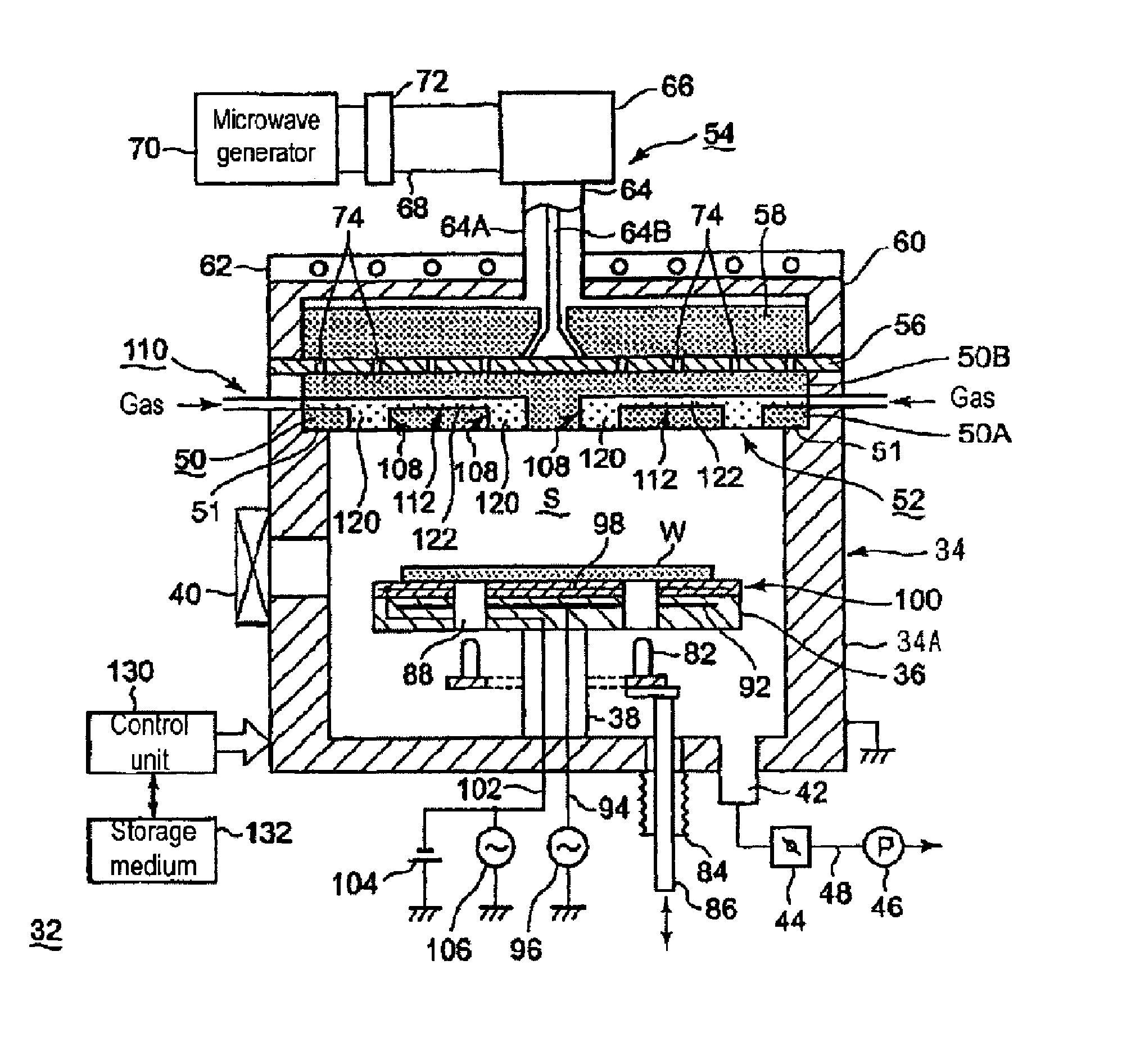
[0069]A plasma processing apparatus 32 shown in FIG. 1 is the apparatus for performing an etching process using a plasma. The apparatus 32 is provided with a vacuum processing container 34, which forms a processing space S hermetically closed inside. This processing container 34 has a tubular container body 34A, in which an upper opening is formed, and a disk-shaped top plate 50, which is attached to the upper opening of this container body 34A. The top plate 50 is attached hermetically against the upper opening of the container body 34A through a sealing member 51, such as an O-ring. The container body 34A is formed from a conductor, such as aluminum, and is grounded.

[0070]Inside of this processing container 34, provided is a placing table 36 on an upper face for placing a semiconductor wafer W as a processing object. This placing table 36 is, for example, formed in a disk-shape from a ceramic, such as alumina, and supported by a column 38 on the bottom portion of the container. On...

second embodiment

[0096]The electromagnetic wave for generating a plasma is not limited to the microwave, and for example, a high-frequency wave with a lower frequency compared to the microwave may be used.

[0097]In the second embodiment of the present invention shown in FIG. 8, the high-frequency wave is used as an electromagnetic wave, and an induction coil 142 is used in the electromagnetic wave supplying system. In FIG. 8, the same reference numbers are provided to the portions with same configuration as those shown in FIG. 1 and the explanation is omitted.

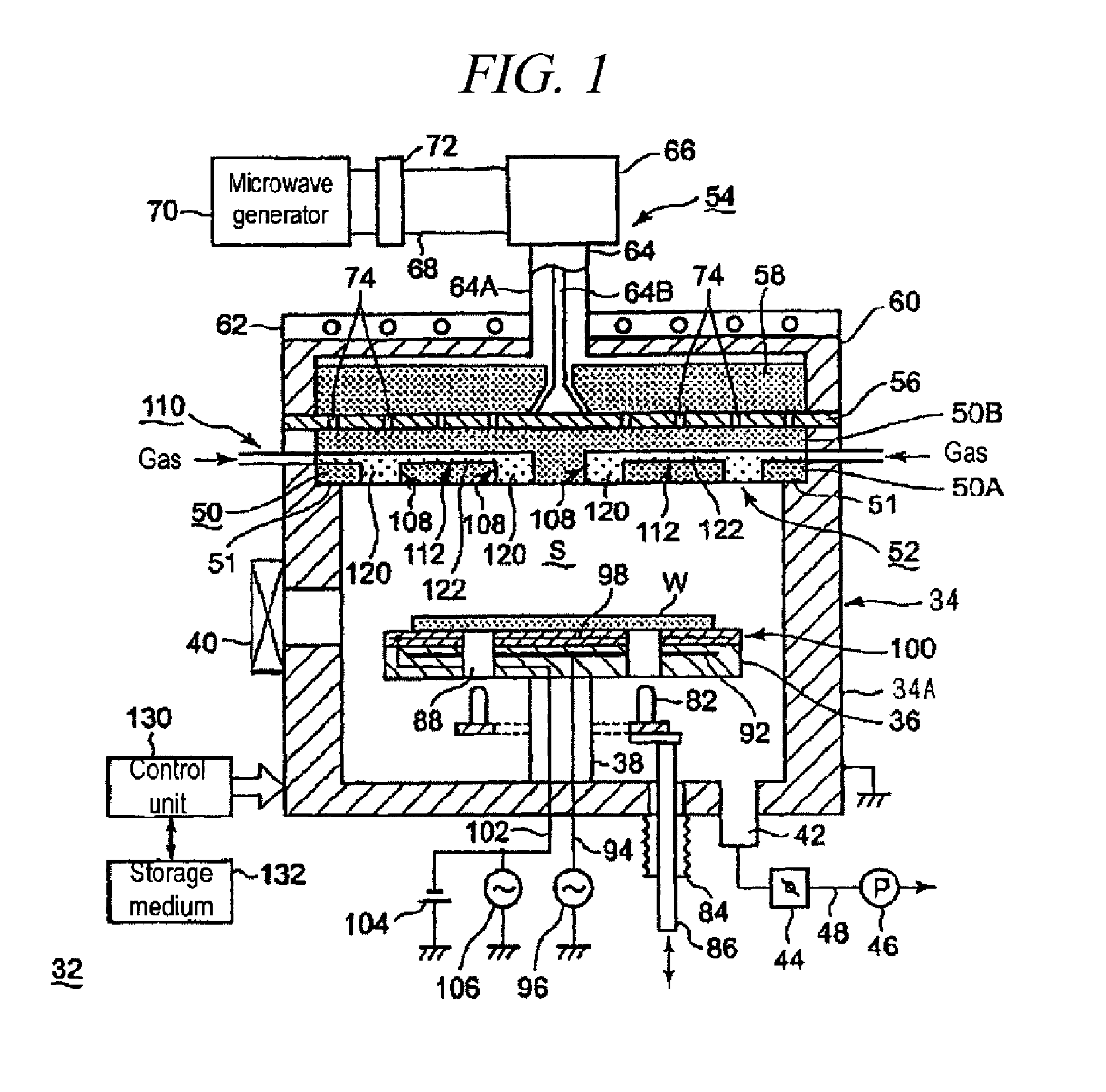
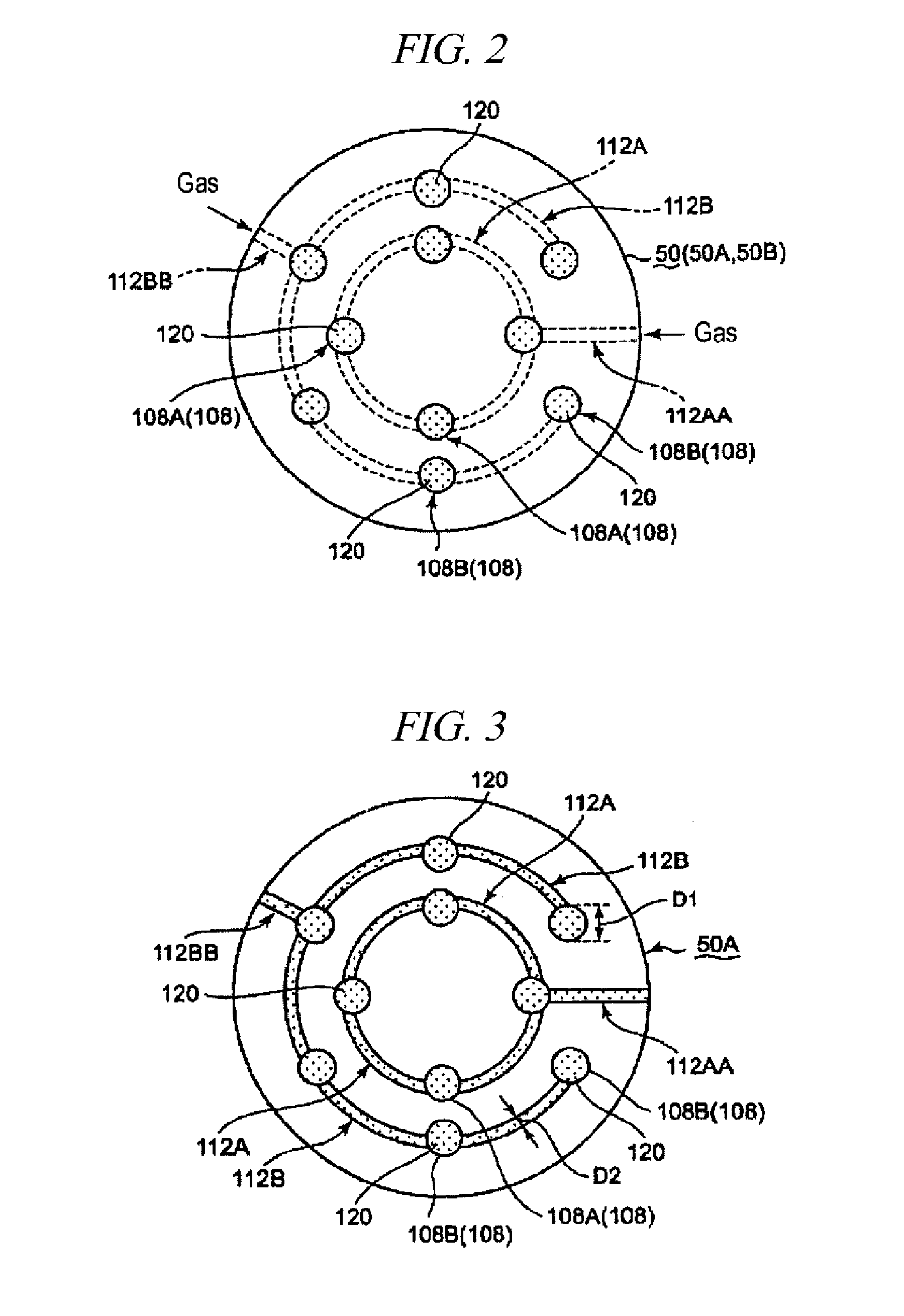
[0098]As shown in FIG. 8, the gas ejection hole 108 and the gas channel 112 of the top plate 50, and the dielectric discharge protection members 120 and 122 filled-in thereof are configured the same as the first embodiment shown in FIG. 1. Meanwhile, the electromagnetic supplying system 54 in this embodiment has the induction coil 142 provided in proximity on the top plate 50 and a high-frequency wave generator 144 connected to the induction coi...

third embodiment

[0100]In the third embodiment of the present invention shown in FIG. 9, a high-frequency wave is used as an electromagnetic wave, as well as a parallel plate type electrode is used as a part of the electromagnetic wave supplying system 54. In FIG. 9, the same reference numbers are used to the configuration same as those in FIGS. 1 and 8, and the explanation is omitted.

[0101]In the third embodiment of the present invention shown in FIG. 9, a cylindrical shape shower head 150 made of a metal is provided, the shower head 150 is attached to the upper portion of the processing container 34 though an insulating material 152. This shower head 150 has a gas ejection face (lower face) 155 with a plurality of gas ejection openings 154 formed to eject the gas into the processing container 34. The electromagnetic supplying system 54 of this embodiment is configured as a high frequency wave supplying system for supplying a high frequency wave applied between both electrodes 36 and 150, with the ...


PUM

PropertyMeasurementUnit
pressureaaaaaaaaaa
diameteraaaaaaaaaa
porous diameteraaaaaaaaaa

Abstract

A manufacturing method of a top plate hermetically attached to an upper opening of a tubular shaped container body for forming a processing container of a plasma processing apparatus is provided. The manufacturing method includes the steps of; preparing a top plate body comprised of a dielectric body for transmitting an electromagnetic wave, and having a gas ejection hole for ejecting a gas into the processing container; forming a discharge prevention member having a discharge prevention member body comprised of a dielectric body having a permeability, and a dense member comprised of a dielectric body without a permeability covering at least a side face of the discharge prevention member body; and attaching the discharge prevention member in the gas ejection hole of the top plate body.

Description

CROSS-REFERENCE TO RELATED APPLICATION[0001]This is a divisional application of U.S. patent application ser No. 12 / 157,660 filed on Jun. 11, 2008, which claims priority under 35 U.S.C. §120 and 35 U.S.C. §365(c) as a continuation of international application number PCT / JP2007 / 050914, filed on Jan. 22, 2007 that claims priority to Japanese patent application number 2006-012965, filed on Jan. 20, 2006.FIELD OF THE INVENTION[0002]The present invention relates to a manufacturing method of a top plate hermetically attached to an upper opening of a tubular shaped container body for forming a processing container of a plasma processing apparatus.BACKGROUND OF THE INVENTION[0003]In recent years, plasma processing apparatuses are used for treatments, such as deposition, etching, or asking, in a manufacturing process of semiconductor products. Specially, a plasma processing apparatus which generates a high-density plasma using a microwave is likely to be used because the plasma is stably gene...

Claims


Application Information

Patent Timeline
Patent Type & Authority Applications(United States)
IPC IPC(8): B32B37/12
CPCB32B37/12H01J37/32192H01J37/3244H01J37/32623H01J2237/0206Y10T156/10
Inventor TIAN, CAIZHONGNOZAWA, TOSHIHISAISHIBASHI, KIYOTAKA
Owner TOKYO ELECTRON LTD
Why Eureka
Try Eureka