LED Lens Design with More Uniform Color-Over-Angle Emission

Active Publication Date: 2013-11-07
BRIDGELUX INC
View PDF5 Cites 25 Cited by
  • Summary
  • Abstract
  • Description
  • Claims
  • Application Information

AI Technical Summary

Benefits of technology

This patent describes an LED device that produces light with improved colord performance. The device has a special lens made from silicone and phosphor particles. The distance between the edges of the LED dies is more than half the length of the lens. The lens is shaped like the top two-thirds of a hemisphere. This design reduces the non-uniformity in the color of the light emitted by the LED device. The device emits blue light and the phosphor particles present in the silicone convert some of this light to yellow light. This yellow light combined with the blue light results in a color at each angle relative to the substrate. The device also has a surface emitter length that is more than twice the length of the lens. The technical effect of this design is an LED device that produces light with consistent color across all angles.

Problems solved by technology

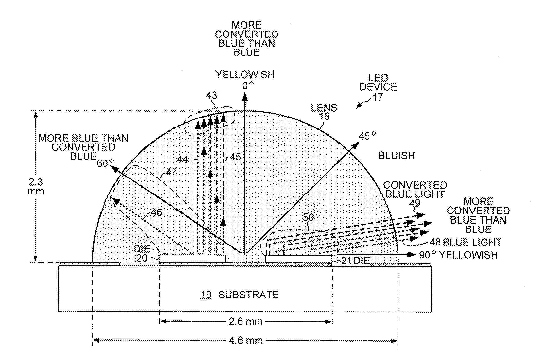
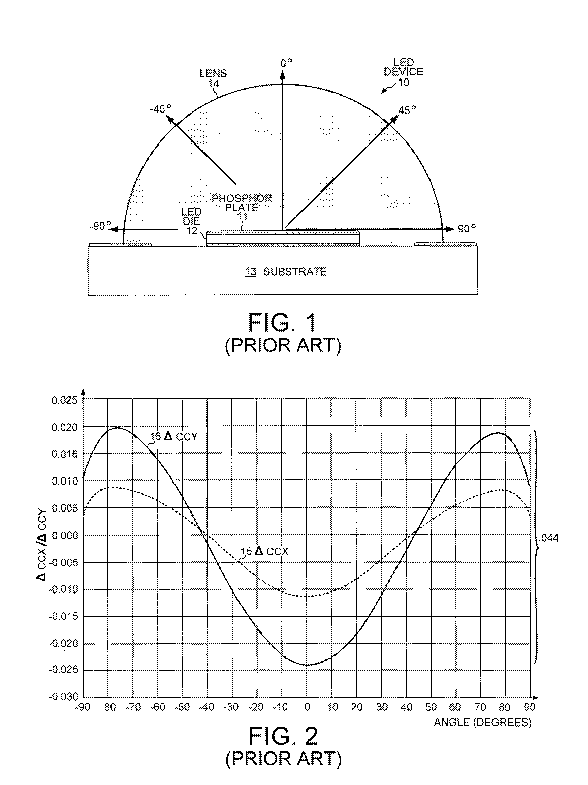
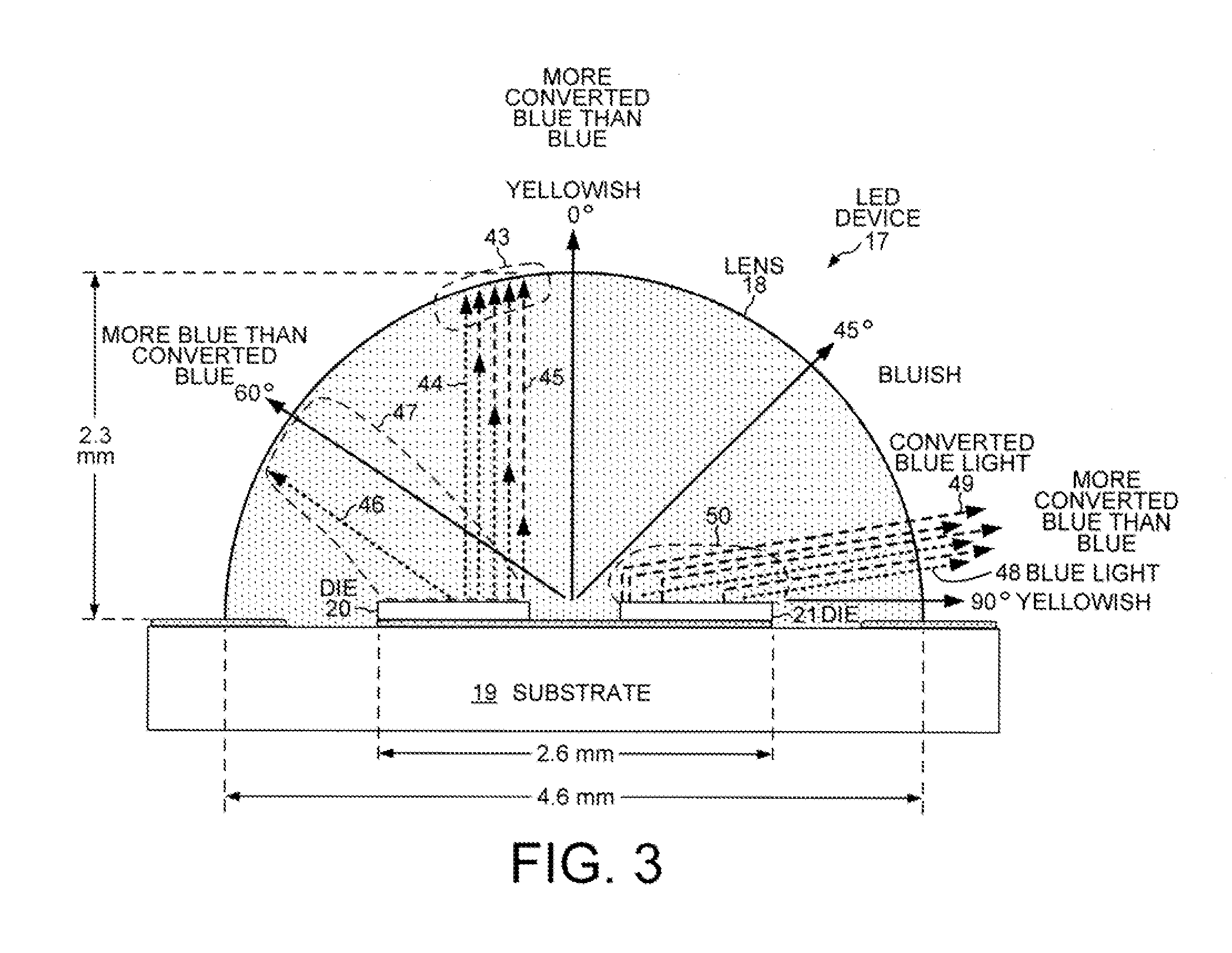
But LED device 17 also exhibits some non-uniformity in its color-over-angle light emission characteristics.
Customers of LED device 17 find the bluish ring to be undesirable.

Method used


Image

  • LED Lens Design with More Uniform Color-Over-Angle Emission
  • LED Lens Design with More Uniform Color-Over-Angle Emission
  • LED Lens Design with More Uniform Color-Over-Angle Emission

Examples


Embodiment Construction

[0030]Reference will now be made in detail to some embodiments of the invention, examples of which are illustrated in the accompanying drawings.

[0031]FIG. 6 is a cross-sectional view of a novel LED device 25 that emits light with a more uniform color over the entire range of emission angles. LED device 25 includes an array of light emitting diode (LED) dies disposed on the upper surface 26 of a substrate 27. For example, LED device 25 includes a two-by-two array of LED dies, including LED dies 28-31. Thermal interface materials 32 are disposed between the LED dies and substrate 27. For example, the thermal interface materials 32 may include a silver-filled epoxy deposited over a layer of Cu—Ni—Au alloy or Cu—Ni—Ag allow. A lens material is then overmolded over the LED dies 28-31 and forms the shape of a lens 33. For example, the lens material is a clear resin encapsulant, such as silicone or epoxy. The lens material is disposed on the upper surface 26 of substrate 27 and over the LE...


PUM


Abstract

An LED device with improved angular color performance has a silicone lens shaped as a portion of a sphere. The lens is molded over an array of LED dies disposed on the upper surface of a substrate. Phosphor particles are disbursed throughout the material used to mold the lens. The distance between farthest apart edges of the LED dies is more than half of the length that the lens extends over the surface of the substrate. The distance from the top of the lens dome to the surface of the substrate is between 57% and 73% of the radius of the sphere. Shaping the lens as the top two thirds of a hemisphere reduces the non-uniformity in the emitted color such that neither of the CIE color coordinates x or y of the color changes more than 0.004 over all emission angles relative to the surface of the substrate.

Description

CROSS REFERENCE TO RELATED APPLICATIONS[0001]This application claims priority under 35 U.S.C. §119 from U.S. Provisional Application No. 61 / 641,219, entitled “LED Lens Design with More Uniform Color-Over-Angle Emission,” filed on May 1, 2012, the subject matter of which is incorporated herein by reference.TECHNICAL FIELD[0002]The present invention relates generally to light-emitting diodes and, more specifically, to a lens design that causes the color of the emitted light to be more uniform over the entire range of angles from which the light is emitted.BACKGROUND INFORMATION[0003]A light emitting diode (LED) is a solid state device that converts electrical energy to light. Light is emitted from active layers of semiconductor material sandwiched between oppositely doped layers when a voltage is applied across the doped layers. The active layers typically include InGaN materials that emit blue light. In order to produce white light, wavelength converting materials commonly known as p...

Claims


Application Information

Patent Timeline
IPC IPC(8): H01L33/50
CPCH01L33/507H01L25/0753H01L33/505H01L33/54H01L2924/0002H01L2924/00H01L33/50H01L33/60H01L33/62H01L2933/0041H01L2933/0058H01L2933/0066
Inventor TONG, TAOZHANG, WENHUIWEST, R. SCOTT
Owner BRIDGELUX INC
Why Eureka
Try Eureka