
Evaporative emissions leak tester and leak test method

a leak tester and leakage technology, applied in the direction of fluid tightness measurement, instruments, machines/engines, etc., can solve the problems of affecting the environment, pursuing a more expensive and time-consuming procedure, and difficult to diagnose the vehicle with current after-sales resources, such as motor-vehicle dealerships, to achieve the effect of eliminating internal piping

Inactive Publication Date: 2013-11-14
MAHLE POWERTRAIN
View PDF2 Cites 12 Cited by
  • Summary
  • Abstract
  • Description
  • Claims
  • Application Information

AI Technical Summary

Benefits of technology

The invention is a tool and method for detecting leaks in fuel evaporative emissions from automotive vehicles. It is affordable and can be used as an aftermarket package. The tool includes a tester package and a VCI pod that can diagnostically command a purge valve and canister-vent solenoid. Overall, this low-cost tool helps to quickly and easily identify fuel evaporative emissions leaks in automotive vehicles.

Problems solved by technology

Gasoline is a volatile substance that generates gases that, if untreated, may be harmful to the environment.
If there is a leak, it may be necessary to pursue a more costly and time-consuming procedure of “smoke-testing” (used to pinpoint the location of the leak) or just a tightening / replacement of a fuel cap of the vehicle.
However, on a vehicle having natural-vacuum-leak detection (NVLD), it is difficult to diagnose the vehicle with current after-sales resources, such as a motor-vehicle dealership.
More specifically, these resources cannot quickly and precisely determine whether the vehicle has a leak in the fuel system of at least a predetermined size after the vehicle is sold and / or serviced.
These resources cannot quickly and precisely also check to determine whether it is necessary to pursue smoke-testing or just a tightening / replacement of the fuel cap.
These resources cannot also provide a solution to test the vehicle at the plant after it has received fuel.

Method used


Image

  • Evaporative emissions leak tester and leak test method
  • Evaporative emissions leak tester and leak test method
  • Evaporative emissions leak tester and leak test method

Examples


Embodiment Construction

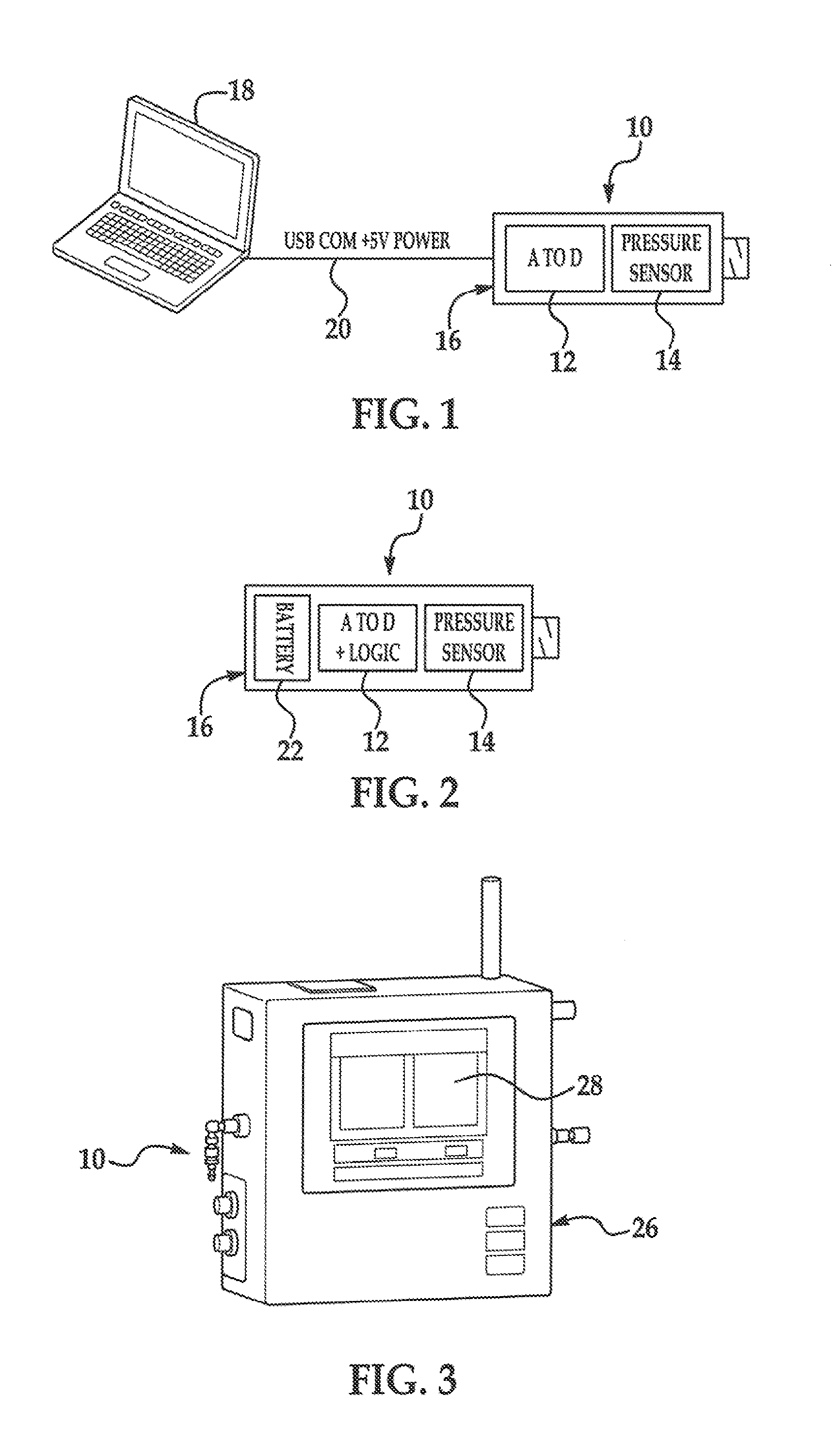
[0034]Referring to the drawing and, in particular, FIG. 1, an embodiment of an evaporative-emissions-leak tester according to the invention is generally indicated at 10. Throughout the figures of the drawing, like numerals are used to indicate like structure of the tester 10. Although the tester 10 is described in detail below and shown in the figures as a low-cost tool or employed as an industrial-stationary (fixed-station) application, those having ordinary skill in the related art should appreciate that the tester 10 and a leak-test method according to the invention (described in detail below) can be employed in any suitable application.

[0035]Referring now specifically to FIG. 1, the embodiment of the tester 10 includes, in general, an analog-to-digital (“A to D”) board 12 and a pressure sensor 14 communicating with the board 12 by a suitable mechanism (such as One that includes a wire or wires or is wireless). The tester 10 includes also a housing, generally indicated at 16, to ...


PUM

PropertyMeasurementUnit
timeaaaaaaaaaa
pressureaaaaaaaaaa
fuel-vapor pressure-rise rateaaaaaaaaaa

Abstract

A tester and method for testing for a leak in an evaporative-emissions system of a motor vehicle comprise a / an power supply, computer, display communicating with the computer, analog-to-digital board communicating with the power supply and computer, pressure sensor communicating with the hoard, housing into which the power supply, board, and sensor are integrated, stationary enclosure, and test connection including a hose to the enclosure. A fuel-vapor pressure-rise rate is recorded with an engine of a motor vehicle turned “off.” A value is recorded that directly correlates with an out-gassing affect created by a volume, blend, and temperature of fuel. A “purge” cycle occurs at idling of the vehicle within a short period of time. The engine applies a vacuum to a fuel-delivery system of the vehicle. Vacuum decay is recorded. A leak rate is determined by off-setting the recorded fuel-vapor pressure-rise rate with the recorded vacuum decay.

Description

CROSS-REFERENCE TO RELATED APPLICATION[0001]This application is based upon and claims benefit of the filing date of U.S. Provisional Patent Application 61 / 645,115 entitled “Evaporative Emissions Leak Tester and Leak Test Method” tiled on May 10, 2012.BACKGROUND OF INVENTION[0002]1. Field of Invention[0003]The invention relates to, in general, an evaporative-emissions system for an automotive vehicle and, in particular, an evaporative-emissions-leak tester and method for detecting an evaporative-emissions leak of fuel vapor from the evaporative-emissions system.[0004]2. Description of Related Art[0005]An automotive vehicle generally includes a fuel system having a fuel tank and fuel-delivery lines. The lines typically include a plurality of conduits and associated connections operatively interconnecting the tank with an internal-combustion engine. A fuel pump is used to deliver fuel under pressure from the tank to the engine via the lines. The vehicle is often powered using gasoline ...

Claims


Application Information

Patent Timeline
Patent Type & Authority Applications(United States)
IPC IPC(8): G01M3/04
CPCG01M3/04F02M25/0809G01M3/025Y10T29/49718
Inventor GEARHART, RAYMOND D.BOLT, LOUIS SCOTTBHARGAVA, SUMIT
Owner MAHLE POWERTRAIN
Features
  • Generate Ideas
  • Intellectual Property
  • Life Sciences
  • Materials
  • Tech Scout
  • Unparalleled Data Quality
  • Higher Quality Content
  • 60% Fewer Hallucinations
Learn More