Throttle body fuel injection system with improved fuel distribution

a fuel injection system and throttle body technology, applied in the direction of electric control, combustion air/fuel air treatment, speed sensing governors, etc., can solve the problem of less than fully vaporized fuel entering the engine cylinder under certain conditions, not providing optimal atomization and mixture delivery to each engine cylinder, and reducing the tendency for idle fuel mixture. , the effect of increasing the pulse width of the fuel injector signal

Active Publication Date: 2013-11-14
MSD LLC
View PDF16 Cites 61 Cited by
  • Summary
  • Abstract
  • Description
  • Claims
  • Application Information

AI Technical Summary

Benefits of technology

[0023]The throttle body assembly includes an idle air control circuit that bypasses throttle blades. The idle air control circuit has an inlet port at the top of the throttle body and an outlet port at the bottom of throttle body. A cross-over port joins the idle air control circuit to one or more bores within the throttle body below the fuel distribution ring. An idle air control motor is used to throttle the amount of air that flows through the idle air control bypass circuit by varying the stem of an idle air control valve between open and shut positions. When the idle air control valve is open, an air / fuel mixture is drawn into the into the intake manifold through the idle air control circuit from the region of the throttle body bores downstream of the fuel injection rings. Because an air fuel mixture rather than air is supplied at idle, the tendency for a lean idle fuel mixture is minimized.
[0024]Additionally, a unique engine control unit “feed forward” algorithm controls the fuel injection as a function of the position of the idle air control motor so that as the IAC valve is opened, the pulse widths of the fuel injector signals are increased. This feature allows the initial open-loop-based fuel mixture supplied by system to be more accurate and eliminates rough unstable idle associated with closed-loop control lag times.

Problems solved by technology

Variations in atmospheric temperature and pressure, engine temperature, load and speed make perfect carburetion nearly impossible to obtain under all driving conditions.
Complicating matters is the fact that gasoline has components with widely varying boiling points, which may result in less than fully vaporized fuel entering the engine cylinders under certain conditions, particularly when the intake manifold is cold.
However, these designs may not provide optimal atomization and mixture delivery to each engine cylinder.
Indeed, the use of venturis with concomitant low pressure zones in fuel injection systems has disadvantages, including imprecise fuel delivery due to the propensity to draw fuel out of the fuel passages downstream of the injectors during “off” periods in the fuel injection cycle and a greater risk for the accumulation of icing within the throttle body under certain conditions.
For this reason, the mixture tends to be too lean during idle conditions, causing rough unstable idle.
As the IAC opens when the engine begins to idle, the fuel delivered to the engine, initially based on the open-loop look-up tables, becomes too lean.
The ECU compensates for the lean idle condition during closed-loop control by measuring post-combustion oxygen levels, but any corrective feedback necessarily lags engine operation under undesirably lean conditions.

Method used


Image

  • Throttle body fuel injection system with improved fuel distribution
  • Throttle body fuel injection system with improved fuel distribution
  • Throttle body fuel injection system with improved fuel distribution

Examples


Embodiment Construction

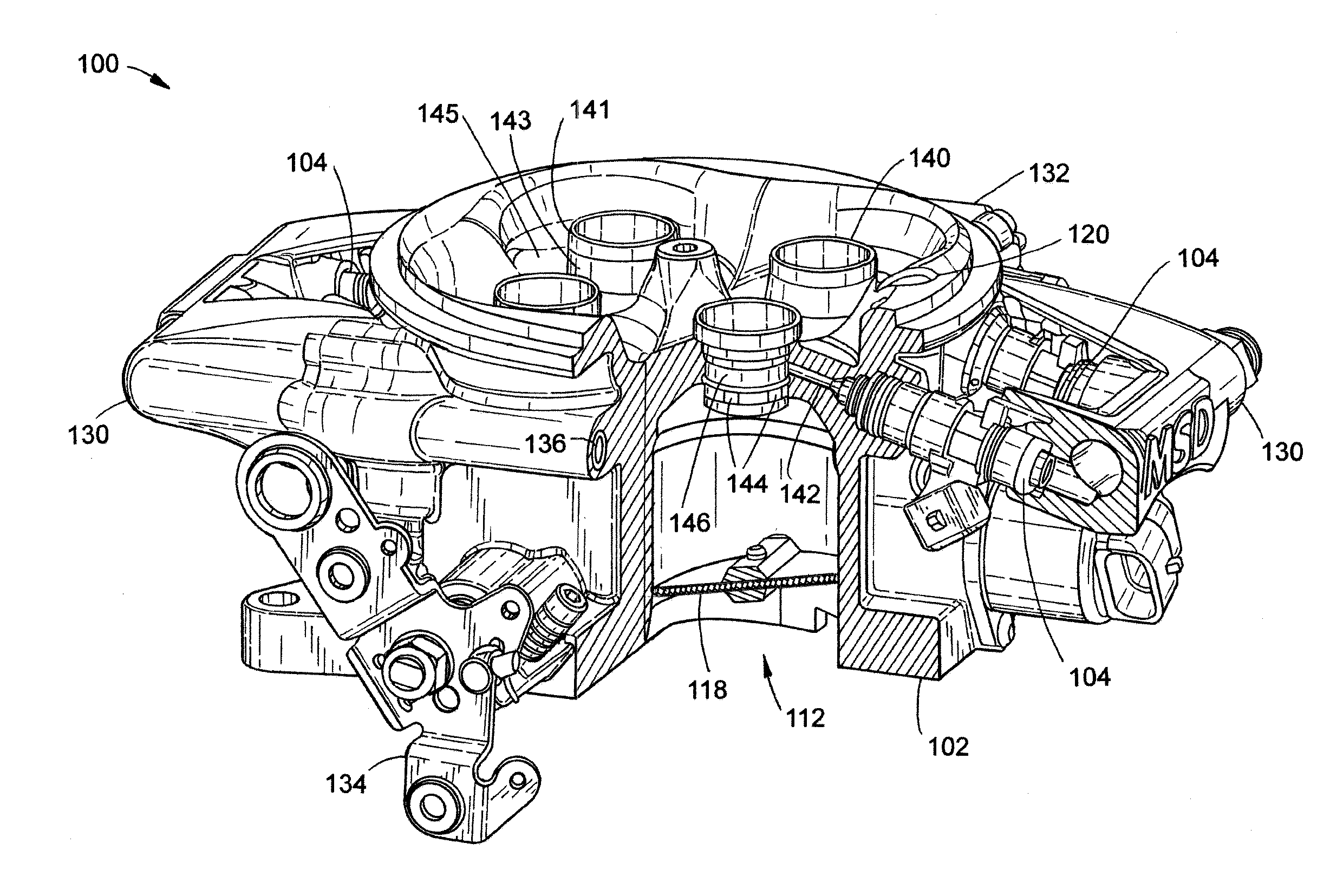
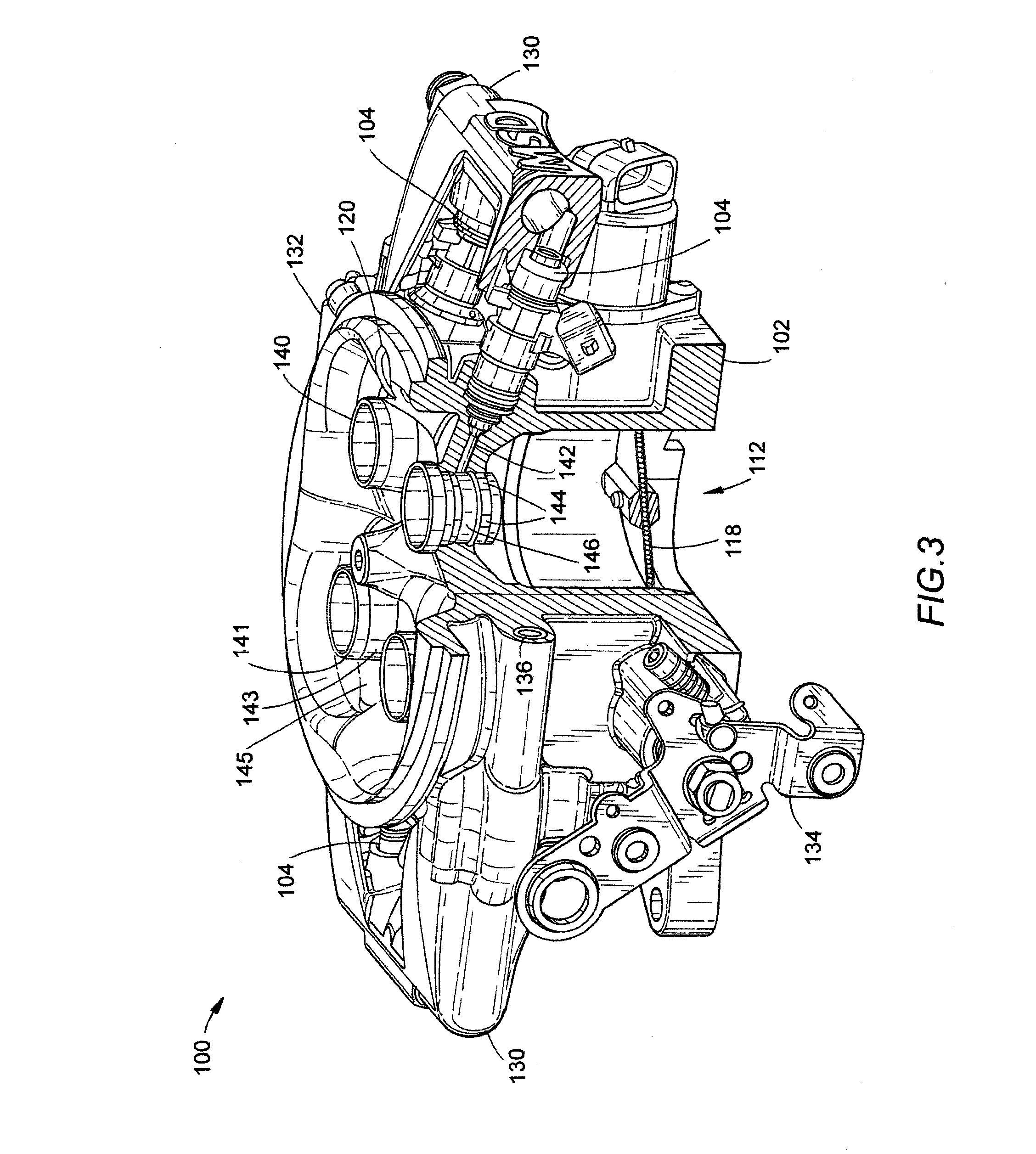
[0034]FIGS. 3-5 illustrate a throttle body fuel injection system 100 according to a preferred embodiment of the invention. Throttle body fuel injection system 100 is a preferably an electronic fuel injection system that is designed and arranged to easily replace four-barrel carburetors. Throttle body 100 is designed to bolt on to any square-bore, four-barrel intake, including the common 4150 and 4160 designs. These intake manifold configurations are found on numerous engines for muscle cars and hot rods, including small and big block engines manufactured by Ford, General Motors, and Mopar. There are also aftermarket intake manifolds available to convert LS engines.

[0035]System 100 includes a throttle body 102 with four main bores 112 (each with a throttle plate 118), left and right fuel rails 130, and an engine control unit (ECU) 132 that is integrated into the side of throttle body 102 opposite the throttle linkage (134). The fuel is fed into one of the fuel rails 130, which is con...


PUM

PropertyMeasurementUnit
inner and outer circumferencesaaaaaaaaaa
circumferenceaaaaaaaaaa
diameteraaaaaaaaaa

Abstract

A throttle body fuel injection system and method that is arranged to easily replace four-barrel carburetors includes a throttle body assembly with four main bores, each with a throttle plate and an associated fuel injector. Each injector feeds fuel into a circular fuel distribution ring via a fuel injection conduit, which introduces pressurized fuel into the air stream. The fuel distribution rings and bores have profiles that avoid constrictions for to prevent low pressure zones according to the Venturi effect. Fuel is injected through downward-facing outlets at or near the bottom end of the rings. The fuel injection rings are two-piece, each formed of an insert pressed into an outer housing. The insert includes axial grooves intervaled about its exterior circumference of insert that are joined by a circumferential groove formed about the insert. The grooves are in fluid communication with a conduit that supplies fuel from a fuel injector.

Description

BACKGROUND OF THE INVENTION[0001]1. Field of the Invention[0002]This invention relates generally to fuel injection systems for internal combustion engines, and in particular to single point throttle body fuel injection systems designed for retrofitting vintage carburetion fuel delivery systems.[0003]2. Background Art[0004]A carburetion fuel delivery system uses a carburetor to supply and meter the mixture of fuel and air in relation to the speed and load of the engine. FIG. 1 illustrates a typical carburetor (10). Carburetor (10) includes one or more barrels (12). A butterfly-type throttle valve (18) is located near the bottom of the barrel (12), the opening and closing of which is controlled through a throttle linkage (not illustrated). Each barrel (12) includes a primary venturi (14) and an annular boost venturi (16), although additional venturis may be used to permit more precise metering of fuel and air under different conditions. Liquid fuel (20) is contained in a float bowl (2...

Claims


Application Information

Patent Timeline
Patent Type & Authority Applications(United States)
IPC IPC(8): F02M69/00B23P17/00
CPCF02M17/00F02M21/04F02M29/04F02M29/06F02M35/10216F02M61/145F02M69/043Y02T10/30Y10T29/49401F02D31/003F02D31/005F02D31/007F02D31/008F02D41/08F02D41/3005F02M69/32
Inventor BENNETT, RICHARD KIRKWEBBER, DOUGLAS DAVID
Owner MSD LLC
Why Eureka
Try Eureka