Apparatus for estimating quantity of state relating to motor, and electric tool

Active Publication Date: 2013-11-14
MAKITA CORP
View PDF27 Cites 12 Cited by
  • Summary
  • Abstract
  • Description
  • Claims
  • Application Information

AI Technical Summary

Benefits of technology

[0007]With the apparatus described above, a feedback loop including the motor model is constructed, and the behavior of the actual motor can be simulated using the motor model. The second quantity of state input into the motor model is adjusted on the basis of the first quantity of state and the third quantity of state in the actual motor such that the third quantity of state is realized under the first quantity of state. As a result, the second quantity of state input into the motor model, or in other words the output of the amplifier, can be used

Problems solved by technology

However, when the motor exhibits unsteady behavior during starting of the motor and in cases where rapidly varying torque acts on the motor or the like, for example, it is difficult to estimate the torque acting on the motor

Method used


Image

  • Apparatus for estimating quantity of state relating to motor, and electric tool
  • Apparatus for estimating quantity of state relating to motor, and electric tool
  • Apparatus for estimating quantity of state relating to motor, and electric tool

Examples


Example

First Embodiment

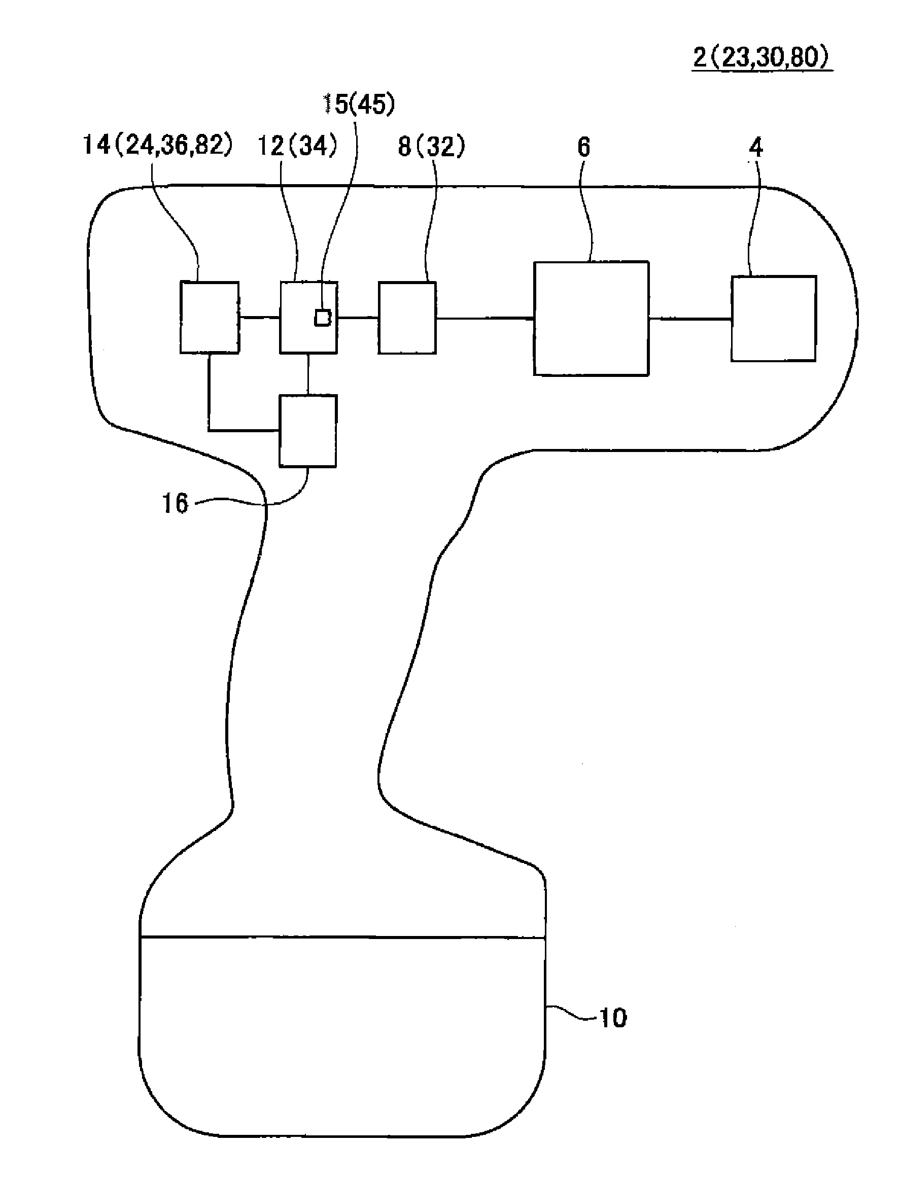
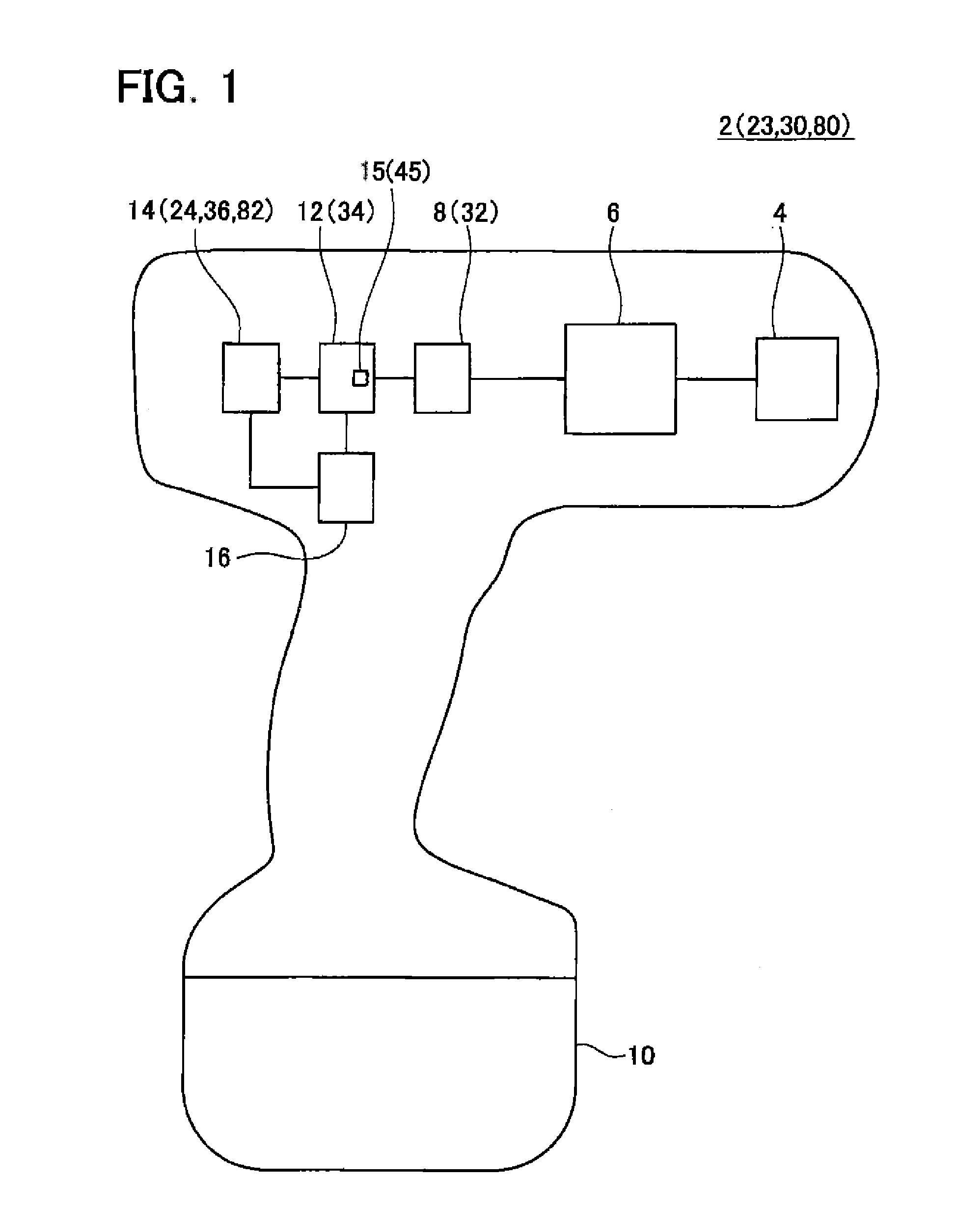
[0030]As shown in FIG. 1, an electric tool 2 according to this embodiment includes a tool unit 4, a power transmission unit 6, a motor 8, a battery 10, a motor driving circuit 12, a monitor circuit 14, and a controller 16. The electric tool 2 may be an impact wrench, an impact hammer, a screwdriver, or the like, for example.

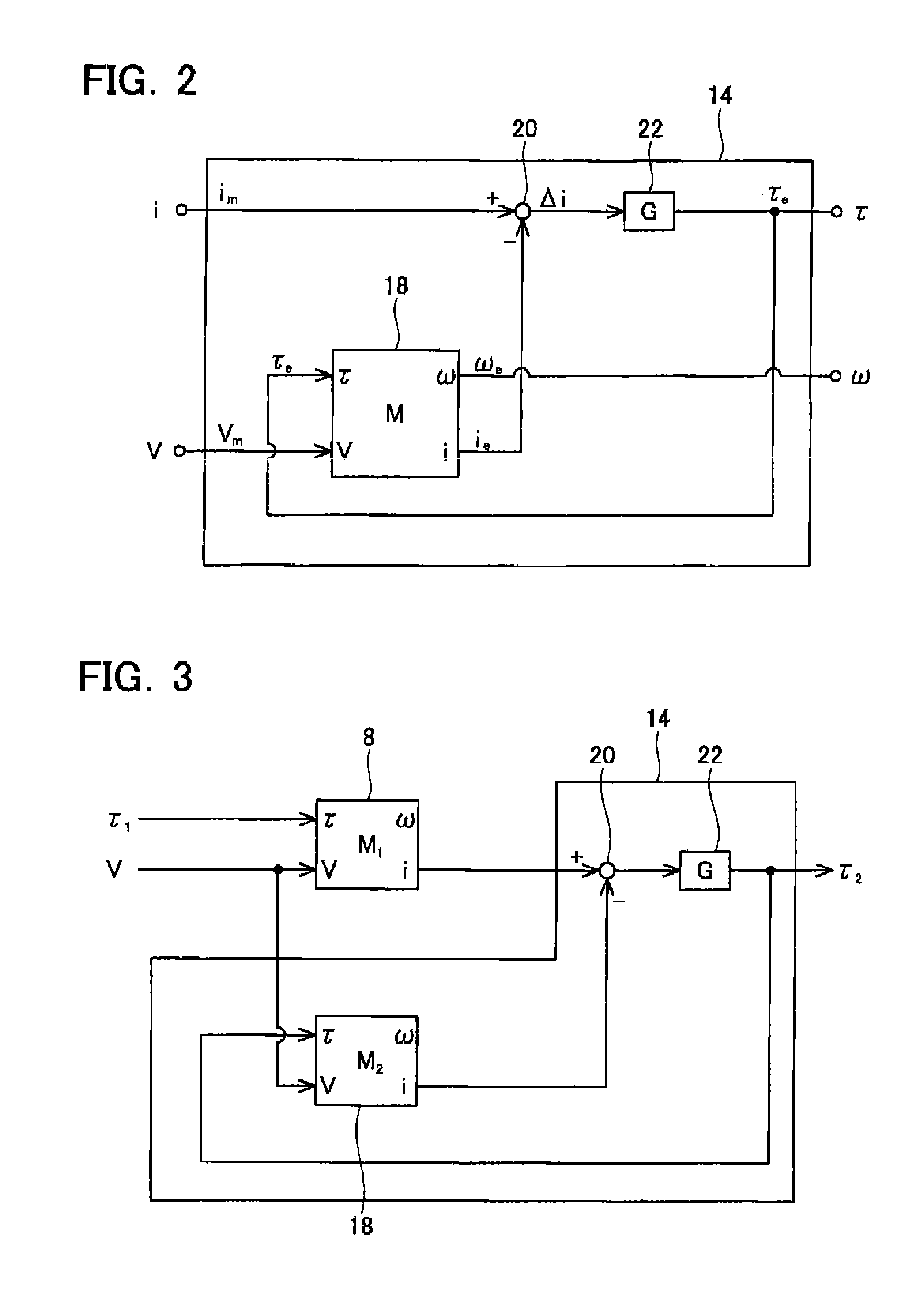
[0031]In the electric tool 2, the motor 8 is driven to rotate by the motor driving circuit 12, and the power transmission unit 6 transmits a rotation of the motor 8 to the tool unit 4. The motor driving circuit 12 includes a current detection unit 15 that detects a current flowing through the motor 8. The monitor circuit 14 estimates a torque τ acting on the motor 8 and a rotation speed ω of the motor 8 on the basis of a voltage V applied to the motor 8 and a current i flowing through the motor 8. The voltage V applied to the motor 8, the current i flowing through the motor 8, the torque τ acting on the motor 8, and the rotation speed ω of the mot...

Example

Second Embodiment

[0048]As shown in FIG. 5, an electric tool 60 according to this embodiment includes the tool unit 4, the power transmission unit 6, a rotation speed sensor 62, the motor 8, the battery 10, a motor driving circuit 66, a monitor circuit 64, and the controller 16. The motor driving circuit 66 according to this embodiment does not include a current detection unit. The rotation speed sensor 62 detects the rotation speed ω of the motor 8 and outputs the detected rotation speed ω to the monitor circuit 64. When the motor 8 is a DC brushless motor, a rotation speed sensor provided as a part of a structure of the motor 8 may be used as the rotation speed sensor 62. The monitor circuit 64 estimates the torque τ acting on the motor 8 and the current i flowing through the motor 8 on the basis of the voltage V applied to the motor 8 and the rotation speed ω of the motor 8, which is input from the rotation speed sensor 62.

[0049]As shown in FIG. 6, the actually measured value Vm o...

Example

Third Embodiment

[0056]An electric tool 30 according to this embodiment is constituted substantially identically to the electric tool 2 according to the first embodiment, shown in FIG. 1. In the electric tool 30 according to this embodiment, a motor 32 is constituted by a DC motor, and a motor driving circuit 34 subjects the motor 32 to PWM control. A monitor circuit 36 outputs a torque and a rotation speed of the motor 32.

[0057]As shown in FIG. 7, the motor driving circuit 34 includes a semiconductor switch 38, a flyback diode 40, a current detecting resistor 42, and an amplifier 44. The current detecting resistor 42 and the amplifier 44 together constitute a current detection unit 45. Note that in this embodiment, a voltage applied to the motor driving circuit 34 is expressed by V′, while a voltage applied to the motor 32 (i.e. a terminal voltage of the motor 32) is expressed by V.

[0058]The semiconductor switch 38 is switched between conduction and non-conduction by the controller ...


PUM


Abstract

The present application discloses an apparatus including: a motor model that reflects a characteristic of a motor and includes at least inputs pertaining to a first quantity of state and a second quantity of state and an output pertaining to a third quantity of state; a comparator that calculates a difference between the third quantity of state in an actual motor and the third quantity of state output from the motor model; and an amplifier that amplifies an output of the comparator at a predetermined gain. The first quantity of state in the actual motor is input into the motor model as the first quantity of state, and an output of the amplifier is input into the motor model as the second quantity of state. The apparatus then uses the output of the amplifier as an estimated value of the second quantity of state in the actual motor.

Description

TECHNICAL FIELD[0001]The technique disclosed in the present application relates to an apparatus for estimating a quantity of state relating to a motor, and an electric tool.BACKGROUND ART[0002]U.S. Pat. No. 4,503,370 discloses a technique for estimating a torque acting on a motor on the basis of a current flowing through the motor.SUMMARY OF INVENTION[0003]When a motor is driven steadily at a fixed rotation speed, a torque acting on the motor can be calculated easily from a current flowing through the motor. However, when the motor exhibits unsteady behavior during starting of the motor and in cases where rapidly varying torque acts on the motor or the like, for example, it is difficult to estimate the torque acting on the motor precisely. The torque can be detected with a high degree of precision by providing a torque sensor, but in this case, increases in cost and apparatus size occur. The torque sensor may also be problematic in terms of durability. Hence, there is need for a tec...

Claims


Application Information

Patent Timeline
IPC IPC(8): H02P31/00
CPCH02P31/00B25F5/00H02P7/29H02P23/14H02P6/06H02P7/295H02P23/12G05B17/02H02P6/34
Inventor SAKO, MASAHIKOYAMAMOTO, HIROKATSUOSADA, TAKAAKI
Owner MAKITA CORP
Why Eureka
Try Eureka