PDMS-Based Stretchable Multi-Electrode and Chemotrode Array for Epidural and Subdural Neuronal Recording, Electrical Stimulation and Drug Delivery

a multi-electrode and chemotrode technology, applied in the field of pdms-based stretchable multi-electrode and chemotrode array for epidural and subdural neuronal recording, electrical stimulation and drug delivery, can solve the problems of limited stretchability, tissue damage, implant damage or loose contact between electrodes and targeted tissues, etc., to facilitate locomotion, improve specificity, and reduce pain

Active Publication Date: 2013-11-14
ECOLE POLYTECHNIQUE FEDERALE DE LAUSANNE (EPFL)
View PDF8 Cites 37 Cited by
  • Summary
  • Abstract
  • Description
  • Claims
  • Application Information

AI Technical Summary

Benefits of technology

[0048]Concerning the second aspect, electrical stimulations have so far been delivered epidurally to alleviate pain or facilitate locomotion after spinal cord injury or Parkinson Disease. The specificity of spinal cord stimulation is limited by the relative large distance between the electrodes and the neural elements. Along the same line, neural activity has been recorded from the epidural space, but the obtained signals showed poor specificity, again due to the large distance between the electrode and the source of the neural signal. The present invention proposes to locate the electrodes closer to and more accurately from the targeted neural structures. This is achieved by positioning the electrodes subdurally to reduce the distance between the electrodes and the targeted neural elements.
[0049]The manufacture of a thin MEA allows the stable positioning of the electrodes close to spinal circuits and pathways while limiting the mechanical stress imposed on neural structures. In order to maintain fluid circulation and thermo-regulation, small holes may be perforated throughout the MEA. The location of the MEA subdurally allows the delivery of drugs through chemotrodes defined as microfluidic channels embedded within the MEA. None of these techniques has been used in the prior art to stimulate the spinal cord electrically or pharmacologically.
[0050]In preferred embodiments of the present invention, conductive PDMS leads covered with gold or other metals are used; this solution demonstrates good stretchability and good conductivity. Other advantages are that it uses exclusively FDA-approved materials (silver, gold and PDMS) and that the contact pads are solderable to medical cable because of the deposited layer of gold. Another advantage of this solution is that the MEA is soft and thin enough to be implanted subdurally without damaging soft surrounding tissues; MEAs with stiffer substrate cannot be implanted there. Another advantage of the subdural location is the capability to deliver more specific electrical stimulations, to obtain improved neural recordings, and to deliver drugs through dedicated chemotrodes at specific segmental locations.
[0051]In general, the device according to the invention should make a tight connection to the tissue containing the cells of the central nervous system. To this end, the device may be provided with a plurality of holes or other surface topographies. These features serve to improve fluid circulation and thermoregulation when the device is implanted subdurally, and enable tissue to grow in through the holes or modulate tissue response by the corresponding topography.

Problems solved by technology

However, they remain too stiff to be used in contact with moving tissues like muscles or the spinal cord, resulting in tissue damage, implant destruction or loose contacts between electrodes and targeted tissues.
This very limited amount of stretchability is due to the gold conductive leads that break easily and is insufficient for applications on the spinal cord.
However the measured impedance of such electrodes is too high for stimulation, and delamination of the gold electrodes will probably occur while applying too high voltages.
The substrate material used is parylene, which exhibits very limited flexibility and stretchability; as a consequence this implant is not stretchable and not suitable for use on the spinal cord.

Method used


Image

  • PDMS-Based Stretchable Multi-Electrode and Chemotrode Array for Epidural and Subdural Neuronal Recording, Electrical Stimulation and Drug Delivery
  • PDMS-Based Stretchable Multi-Electrode and Chemotrode Array for Epidural and Subdural Neuronal Recording, Electrical Stimulation and Drug Delivery
  • PDMS-Based Stretchable Multi-Electrode and Chemotrode Array for Epidural and Subdural Neuronal Recording, Electrical Stimulation and Drug Delivery

Examples


Embodiment Construction

General Remarks

[0075]In the following, preferred embodiments of PDMS-based stretchable microelectrode arrays (SMEA) for spinal cord stimulation are described. Such SMEAs were fabricated and tested in vivo on the spinal cord of rats. However, the invention is by no means limited to SMEAs suitable for implantation in rats or other rodents, and SMEAs of the type described in the following may also be employed with other vertebrates, including humans. Use of such SMEAs is not limited to implantation at the spinal cord. SMEAs of the type described here may also be employed in other body regions where they are subjected to strains.

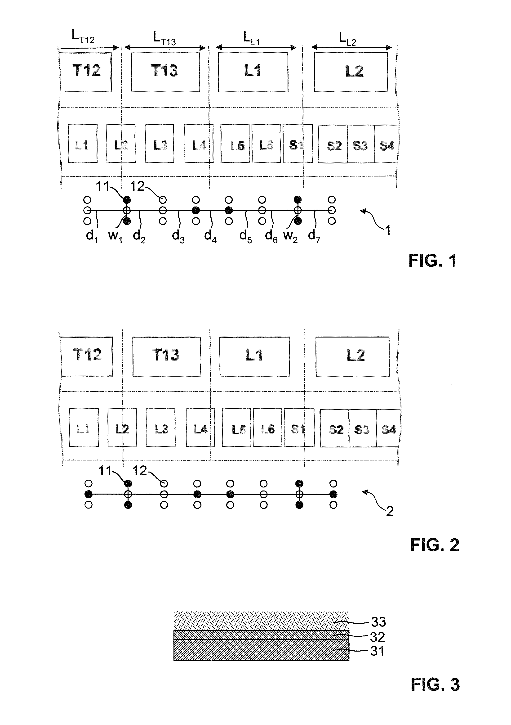
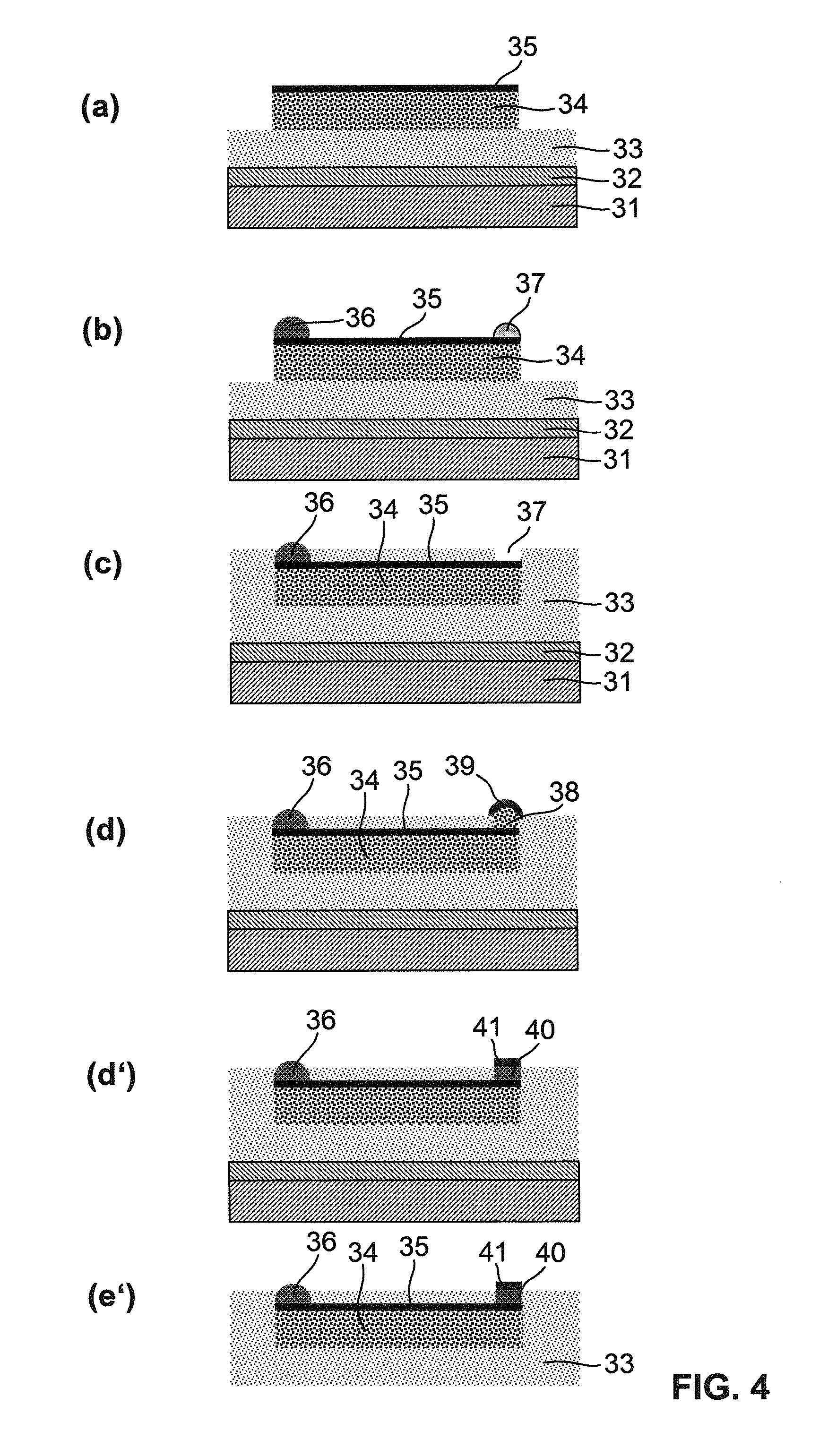
[0076]The monolithic PDMS structure of the SMEA contained conductive PDMS (cPDMS) tracks, gold or platinum or platinum-iridium electrodes and contact pads connected to a head connector via medical fine wires. A PDMS substrate was used to reduce the mismatch between the mechanical properties of the implant and the spinal cord. The elastic and electrical propertie...


PUM

PropertyMeasurementUnit
total thicknessaaaaaaaaaa
thicknessaaaaaaaaaa
thicknessaaaaaaaaaa

Abstract

A hopper having a passage through which a medicine can be passed downward is provided. A part of a lower portion of the hopper is a deformable portion having flexibility, and the deformable portion is deformable so as to open and close the passage. According to this configuration, the deformable portion that is a part of the hopper is deformed to open and close the passage. Thus, there is no portion such as an opening and closing plate on which the medicine remains, thereby preventing a gap in which the medicine remains from being formed in the hopper, and preventing the medicine from easily remaining in the hopper.

Description

TECHNICAL FIELD[0001]The present invention relates to a device that is suitable for the electrical and / or pharmaceutical stimulation of the central nervous system, especially the spinal cord, or for recording neuronal signals, and to related methods of its use and manufacture.PRIOR ART[0002]Since Galvani's experiment on frog legs in the late 1780s, electrical stimulation of tissue or cells has been widely used by physiologists to investigate and understand the electrical properties of living organs and organisms. As a result, the first cardiac pacemaker was implanted in 1958 and now, more than 50 years later, pacemakers are improving the life of 600,000 patients every year. During the 1970s Michelson convinced the scientific community that meaningful sound could be transmitted to the brain by electrical stimulation of the cochlear nerve. Since then, over 200,000 people have received a cochlear implant and are able to understand human speech. Thanks to recent advances in neuroscience...

Claims


Application Information

Patent Timeline
Patent Type & Authority Applications(United States)
IPC IPC(8): A61B5/04A61N1/05A61N1/30B05D7/00
CPCA61B5/04001B05D7/00A61N1/0551A61N1/303A61B5/407A61B2562/046A61B2562/125A61B2562/164A61B2562/166A61B2562/0215A61B5/24H05K1/0272H05K1/0283H05K1/095H05K3/1233H05K3/246H05K3/4664H05K3/4682H05K2201/0162H05K2201/0329H05K2203/016
Inventor VOROS, JANOSLARMAGNAC, ALEXANDRECOURTINE, GREGOIREMUSIENKO, PAVEL
Owner ECOLE POLYTECHNIQUE FEDERALE DE LAUSANNE (EPFL)
Why Eureka
Try Eureka