Resonant switching power supply device

a power supply device and resonant technology, applied in the direction of electric variable regulation, process and machine control, instruments, etc., can solve the problems of no longer being able to obtain a voltage conversion ratio m of one or more, extreme high temporal change rate, worst case of element destruction, etc., and achieve high reliability power supply devices

Active Publication Date: 2013-11-21
FUJI ELECTRIC CO LTD
View PDF4 Cites 42 Cited by
  • Summary
  • Abstract
  • Description
  • Claims
  • Application Information

AI Technical Summary

Benefits of technology

[0022]The resonant switching power supply device with the heretofore described configuration is such that it is possible to detect in advance that the polarity of the resonant current will be inverted by detecting the timing of an inversion of the polarity of the winding voltage, whose phase is further advanced than that of the resonant current, and it is thus possible, in the event that the first or second switch is in an on-state, to turn the switch off before the polarity of the resonant current is inverted. Because of this, it no longer happens that a recovery current flows through the diode connected in parallel to the switch, generating a large di / dt, and it is thus possible to provide a more highly reliable power supply device.
[0023]Also, as the switch is not turned off until it is detected in advance that the resonant current will be inverted by detecting an inversion of the polarity of the winding voltage, whose phase is further advanced than that of the resonant current, the on-state of the switch is guaranteed even when there is a light load.
[0024]Also, as the decision as to whether to activate a forcible turning off of the first or second switch at a timing immediately before the inversion of the polarity of the resonant current depends on the output of the winding voltage, it does not happen that there is a failure to prevent the inversion of the resonant current due to delay or noise.
[0025]The heretofore described and other objects, characteristics, and advantages of the invention will be made clear by the attached drawings representing embodiments preferred as examples of the invention, and by the following related description.

Problems solved by technology

As the recovery current has an extremely high temporal change rate, that is, di / dt, excessive stress is placed on the switches Q1 and Q2, leading in the worst case to element destruction.
When adopting a minimum frequency setting in the vicinity of f1 in an attempt to avoid an inversion of the resonant current, it is no longer possible to obtain a voltage conversion ratio M of one or more.
That is, it is not possible to secure the necessary output voltage when the input voltage is low, and as the possible control range is reduced because of this, it is not desirable to adopt a minimum frequency setting in the vicinity of f1.

Method used


Image

  • Resonant switching power supply device
  • Resonant switching power supply device
  • Resonant switching power supply device

Examples


first embodiment

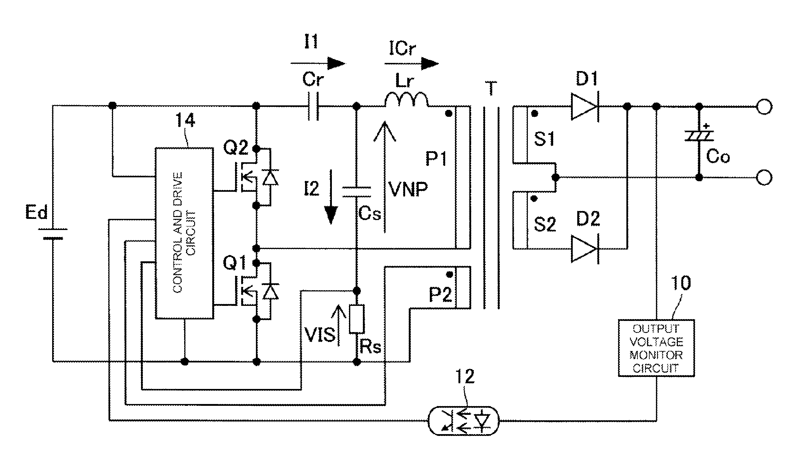
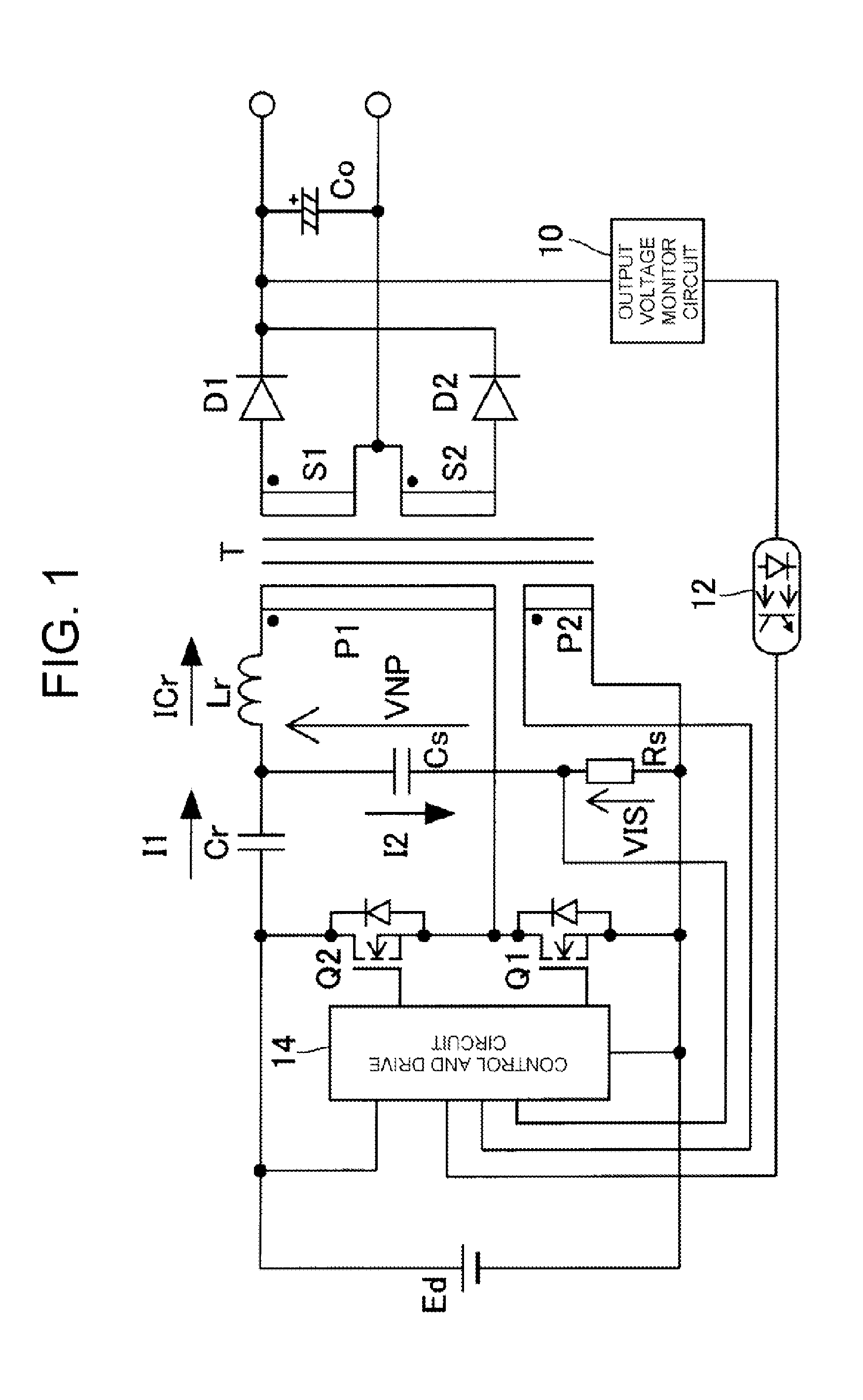
[0038]The resonant switching power supply device includes as a main circuit two switches Q1 and Q2 of a half-bridge configuration connected in series to either end of a direct current output direct current power supply Ed. A built-in parasite diode or external freewheeling diode is connected in anti-parallel to each of the switches Q1 and Q2. In the example shown in the drawing, the switches Q1 and Q2 are represented as MOSFETs (Metal-Oxide Semiconductor Field-Effect Transistors).

[0039]A series circuit of a resonant capacitor Cr, a resonant inductor Lr, and a first winding P1 on the primary side of a transformer T configures a resonant circuit, and is connected to both ends of the high side switch Q2. The first winding P1 has an exciting inductor and leakage inductor of the transformer T as an equivalent circuit. The resonant inductor Lr may be configured of the leakage inductor.

[0040]The transformer T also includes on the primary side thereof a second winding P2. The second windin...

third embodiment

[0072]FIG. 7 is a circuit diagram showing an example of a configuration of a resonant switching power supply device according to a In FIG. 7, components the same as or equivalent to components shown in FIG. 1 are given the same reference signs, and a detailed description thereof will be omitted.

[0073]The resonant switching power supply device according to the third embodiment has a configuration wherein the transformer T is connected in parallel to the low side switch Q1, as shown in FIG. 7. That is, the series circuit of the resonant inductor Lr, the first winding P1 on the primary side of the transformer T, and the resonant capacitor Cr configuring the resonant circuit is connected to both ends of the low side switch Q1. The resistor Rs that detects the resonant current ICr is inserted into the series circuit, configuring a resonant current detector unit. A connection point of the resistor Rs and resonant capacitor Cr is connected to the control and drive circuit 14, and the dete...


PUM


Abstract

A winding voltage arising in a first winding on the primary side of a transformer is detected in a winding voltage detector unit formed of a second winding, and current flowing through a resonant circuit is detected in a resonant current detector unit formed of an auxiliary capacitor and a resistor. The timing at which the polarity of the detected winding voltage is inverted is detected in a control and drive unit, and the time at which the polarity of the resonant current, whose phase is delayed with respect to that of the winding voltage, will be inverted is determined in advance. In the event that there is a switch in an on-state when the timing immediately before the inversion of the polarity of the resonant current is detected from the output of the resonant current detector unit, the control and drive unit forcibly turns off the switch.

Description

TECHNICAL FIELD[0001]The present invention relates to a current resonant DC-DC converter type resonant switching power supply device that includes a series resonant circuit having a resonant inductor and resonant capacitor.BACKGROUND ART[0002]Owing to characteristics such as small size, lightness, and low price, switching power supply devices are used as power supplies in a large number of electronic instruments. Among these, resonant switching power supply devices are widely used as power supplies for liquid crystal display devices, flat panel displays (flat screen televisions) such as plasma display panels, and personal computers, as the resonant switching power supply devices can realize low noise and high conversion efficiency.[0003]FIG. 8 is a circuit diagram of a general resonant switching power supply device, FIG. 9 is a diagram showing the input voltage conversion ratio of voltage generated in a transformer winding in response to a change in control frequency, and FIGS. 10A ...

Claims


Application Information

Patent Timeline
Patent Type & Authority Applications(United States)
IPC IPC(8): H02M1/32H02M3/335
CPCH02M1/32H02M3/33507Y02B70/10H02M1/0058H02M3/33571H02M3/01
Inventor SATO, TADAHIKOOHASHI, HIDETOMO
Owner FUJI ELECTRIC CO LTD
Why Eureka
Try Eureka