Turbocompressor Antisurge Control by Vibration Monitoring

a technology of vibration monitoring and turbocompressor, which is applied in the direction of electric control, liquid fuel engines, instruments, etc., to achieve the effect of effective detection of turbocompressor surg

Active Publication Date: 2013-11-21
COMPRESSOR CONTROLS LLC
View PDF7 Cites 31 Cited by
  • Summary
  • Abstract
  • Description
  • Claims
  • Application Information

AI Technical Summary

Benefits of technology

[0012]An object of the present invention is to provide a method and apparatus for effectively detecting turbocompressor surge using mechanical signals such as displacement and vibration. Another object of this invention is to provide antisurge control based on information gleaned from these mechanical signals.
[0015]When surge is detected using this method, a control system can take corrective action to extract the compressor from its surge condition.
[0018]The technique of the present invention allows the system to monitor specific frequency bands that tend to only respond to surge. These bands can be set for each controller based on the ambient noise floor and result in significantly higher signal-to-noise ratio when surge occurs.

Problems solved by technology

That is, effectively across the full span and effectively around the entire annulus of the compressor, the fluid flow direction reverses, or at least drops to a very low level, because the compressor cannot maintain an adequate differential pressure from inlet to outlet.
Significant axial displacement and vibration results.

Method used


Image

  • Turbocompressor Antisurge Control by Vibration Monitoring
  • Turbocompressor Antisurge Control by Vibration Monitoring
  • Turbocompressor Antisurge Control by Vibration Monitoring

Examples


Embodiment Construction

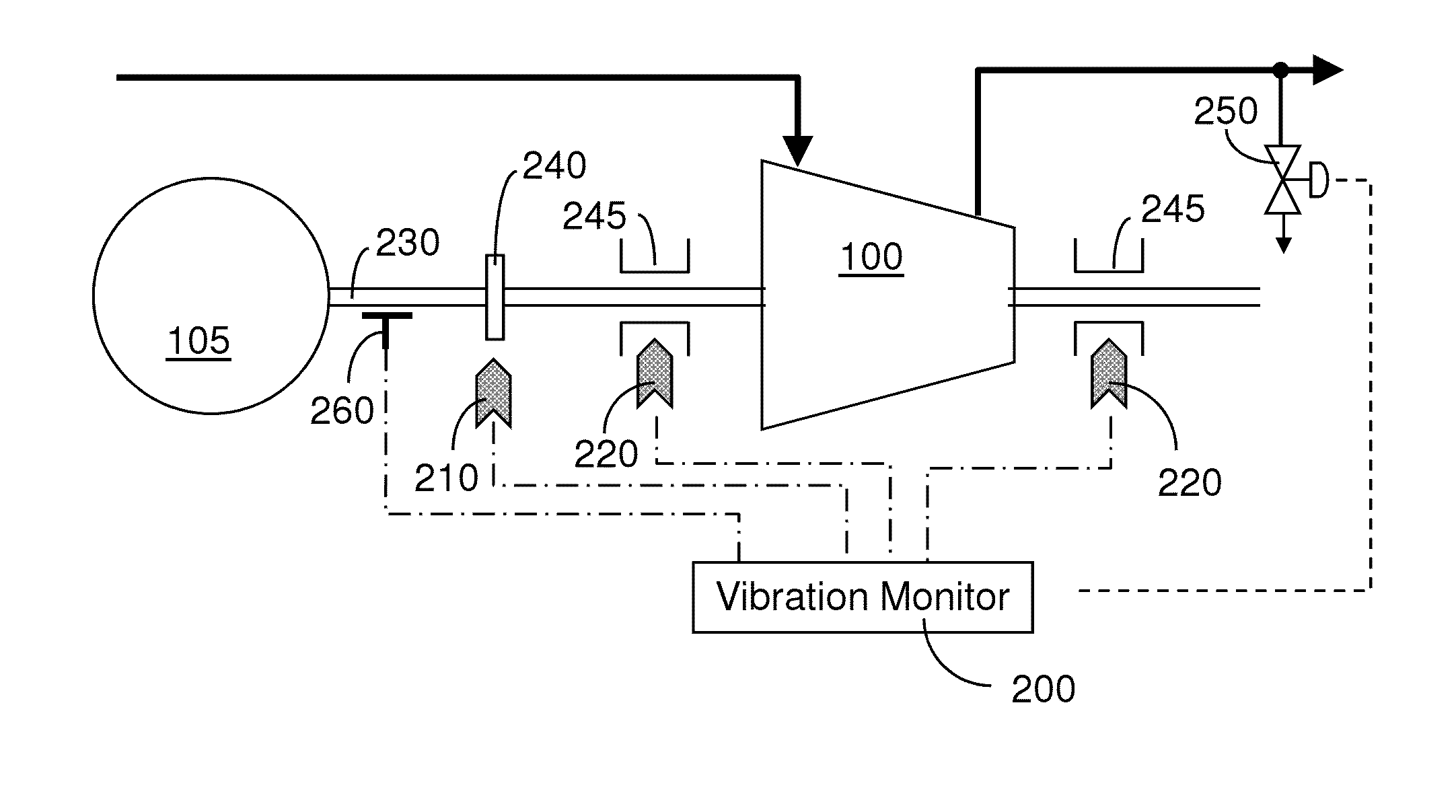
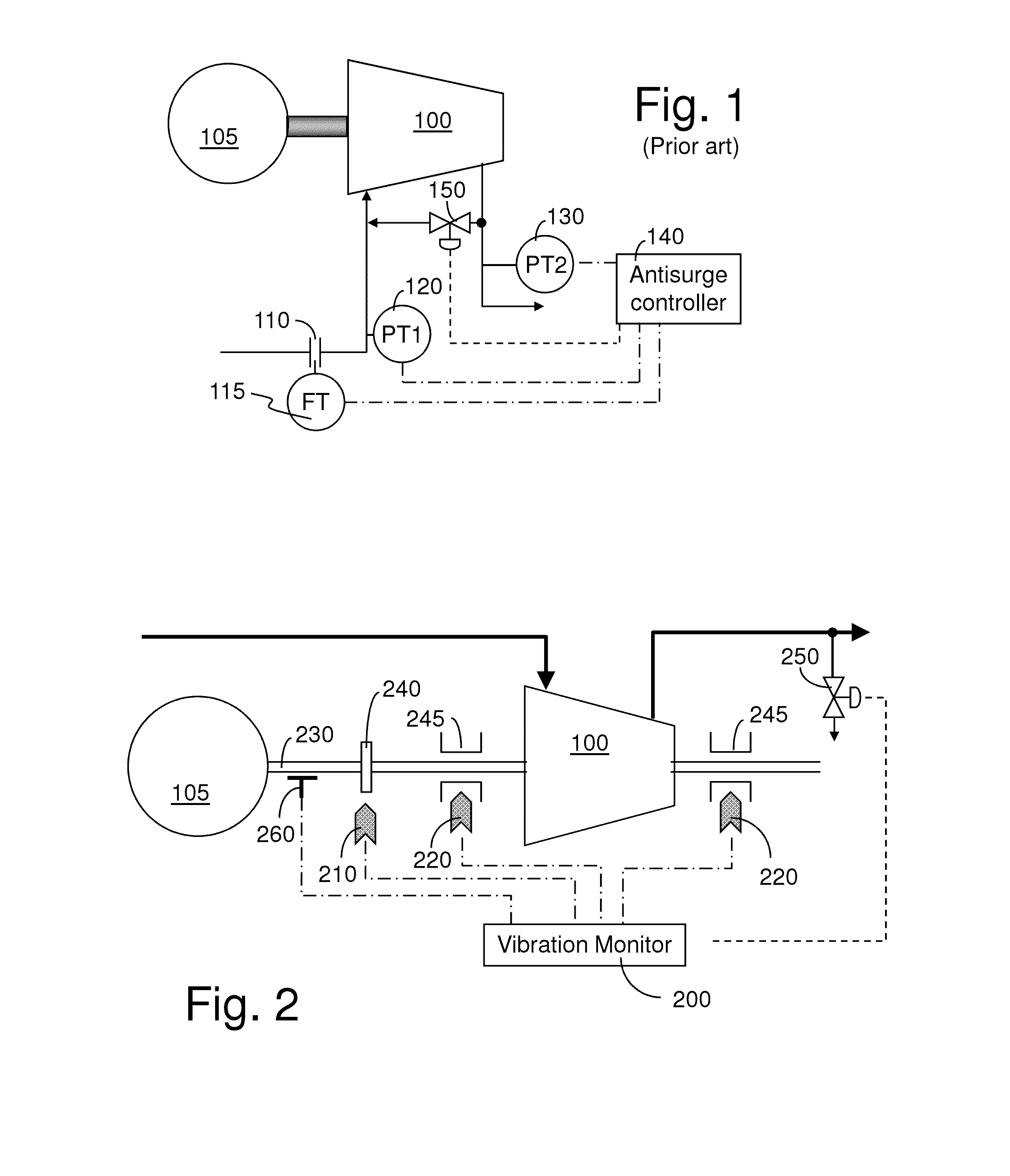
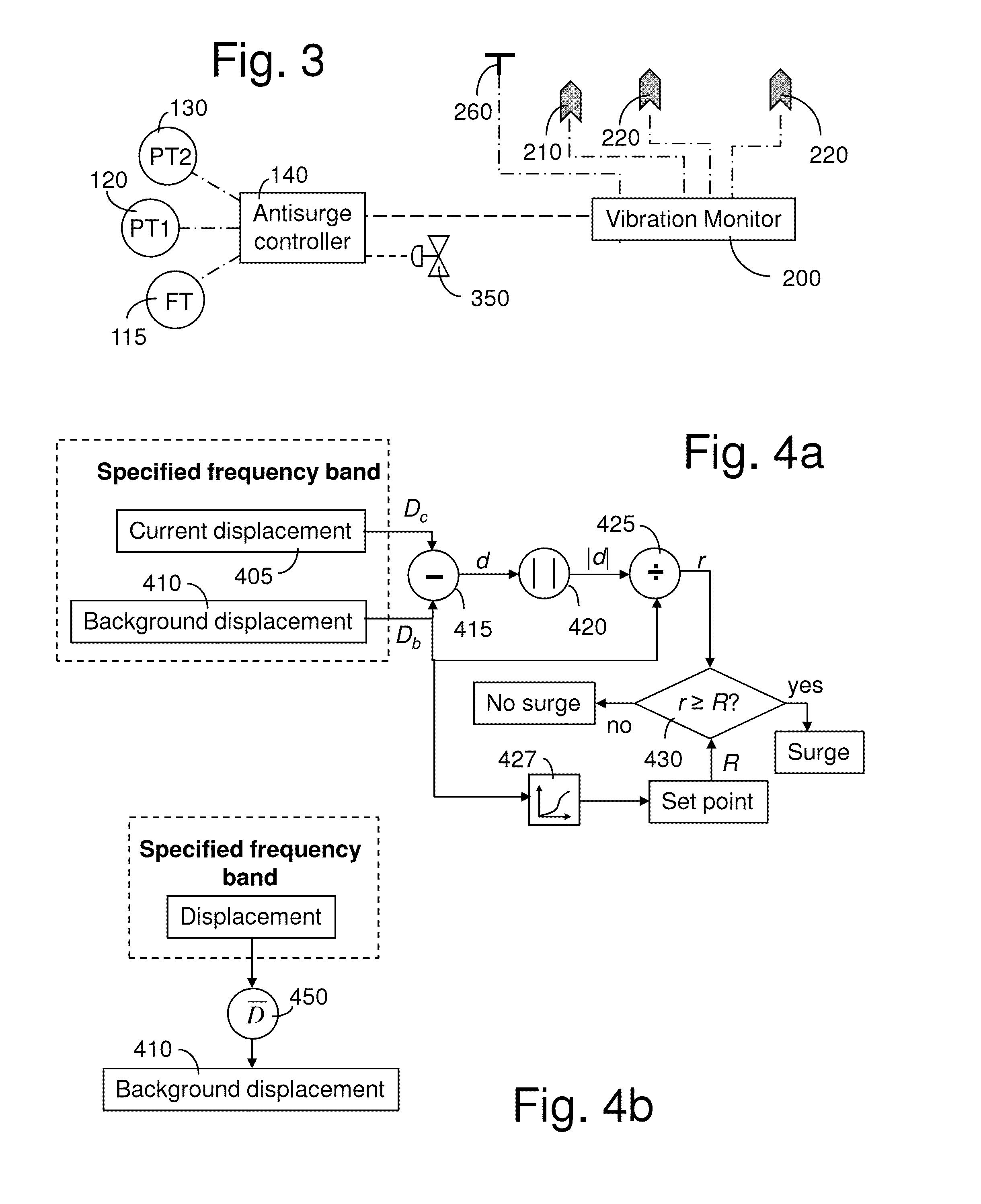
[0037]The compressor 100 is equipped with a vibration monitoring system, including a vibration monitor 200 and one or more vibration sensors 210, 220, such as an axial displacement, velocity, or acceleration sensor 210, and radial displacement, velocity, or acceleration sensors 220. The vibration monitor 200 provides signal conditioning for the purpose of more accurately detecting surge. Additionally, the vibration monitor provides a signal that may be conveyed to an antisurge controller 140, or directly as a set point to the antisurge valve 150, 250 to avoid, prevent, or recover from a compressor surge. Thus, the vibration monitor 200 may be part of a monitoring system that generates a compressor stability indication based on the mechanical measurements described above. The sensors 210, 220 may include sensors 210, 220 operatively attached to the bearings of compressor rotor shaft 230. A thrust bearing 240 as well as a plurality of radial bearings 245, are illustrated along the com...


PUM


Abstract

The proposed mechanical method of turbocompressor surge detection uses vibration signals from vibration monitoring equipment mounted on the compressor components to detect a surge event and provide antisurge control thereby. This method utilizes only mechanical information to identify surge, as compared to present day antisurge controllers that use compressor thermodynamic information such as flow, pressure, and temperature to locate a compressor's operating point on a compressor map compared to a surge region.

Description

CROSS REFERENCE TO RELATED APPLICATIONS[0001]Not applicable.BACKGROUND OF THE INVENTION[0002]1. Field of the Invention[0003]The present invention relates generally to an automatic control scheme. More particularly the present invention relates to a method and apparatus for protecting a turbocompressor from surge by monitoring crucial vibration information and acting thereon.[0004]2. Background Art[0005]Compressor surge and stall represent unstable operating regimes of axial and centrifugal turbocompressors. Either mode of instability may lead to compressor damage. First, rotor vibration due to the unsteady flow of stall can cause flutter and associated fatigue. The flow reversal of surge results in an increase in temperature within the compressor. At the same time, the reversed flow and pressure variations between the intake and discharge ends of the compressor cause rapid changes in axial thrust, thereby risking damage to the thrust bearing and causing blades or vanes to rub on the...

Claims


Application Information

Patent Timeline
Patent Type & Authority Applications(United States)
IPC IPC(8): F04D29/66F04D17/10
CPCF04D27/001F02D41/0007F04D27/00F04D27/02F04D27/0223G01H1/003
Inventor JOHNSEN, JAMES R.
Owner COMPRESSOR CONTROLS LLC
Why Eureka
Try Eureka