

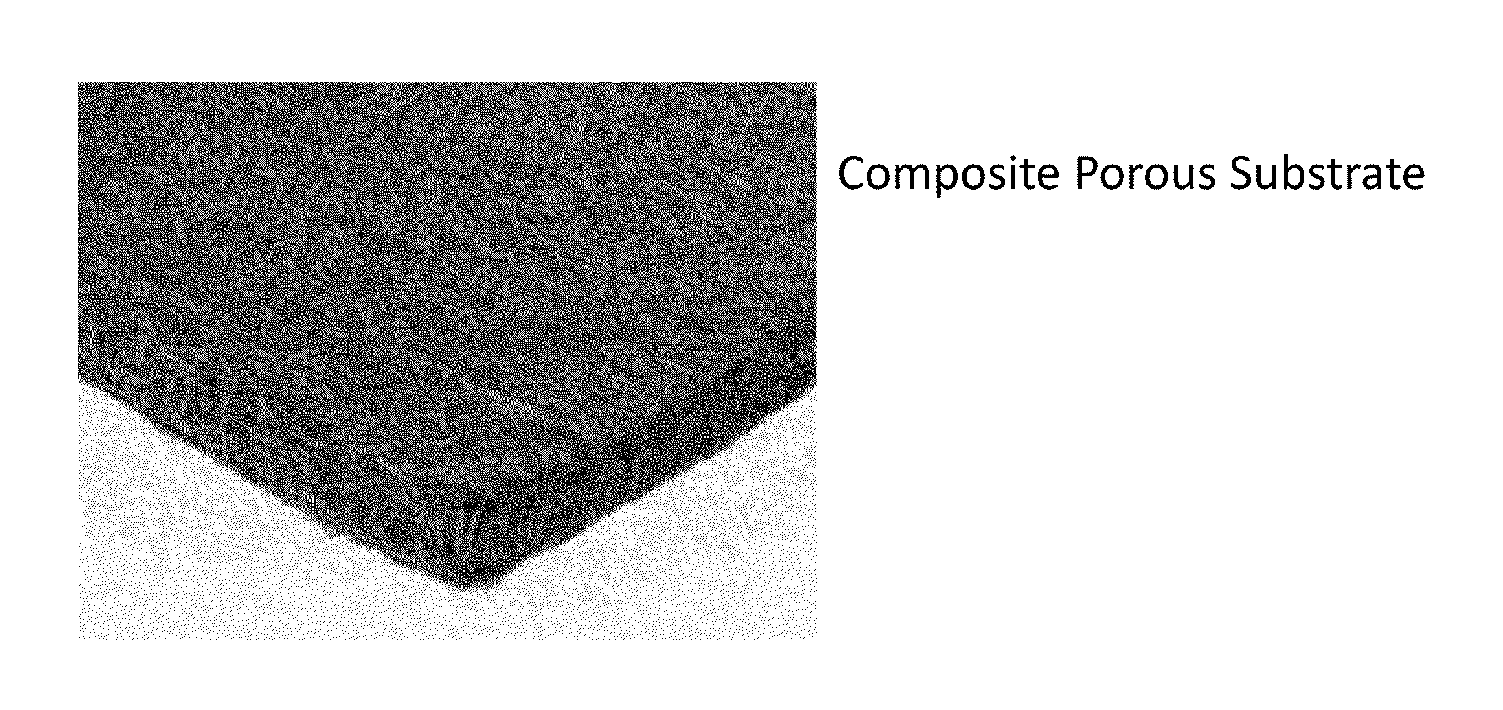
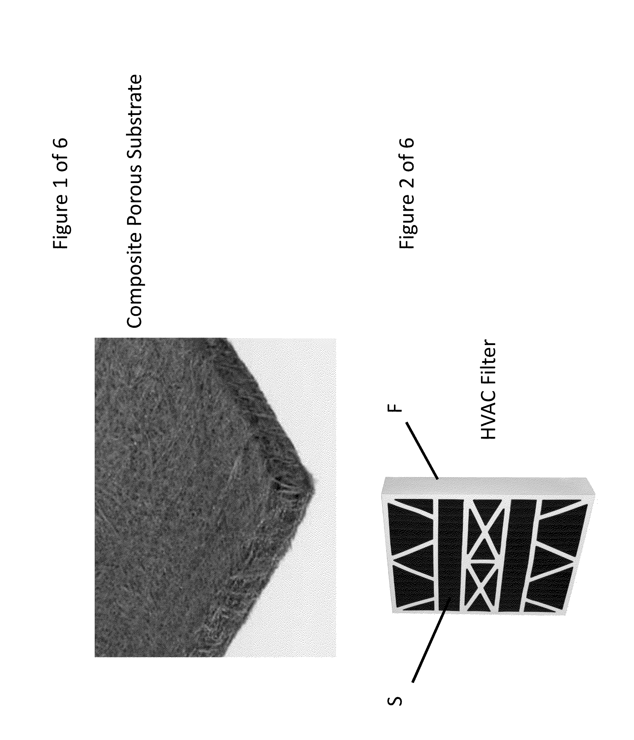
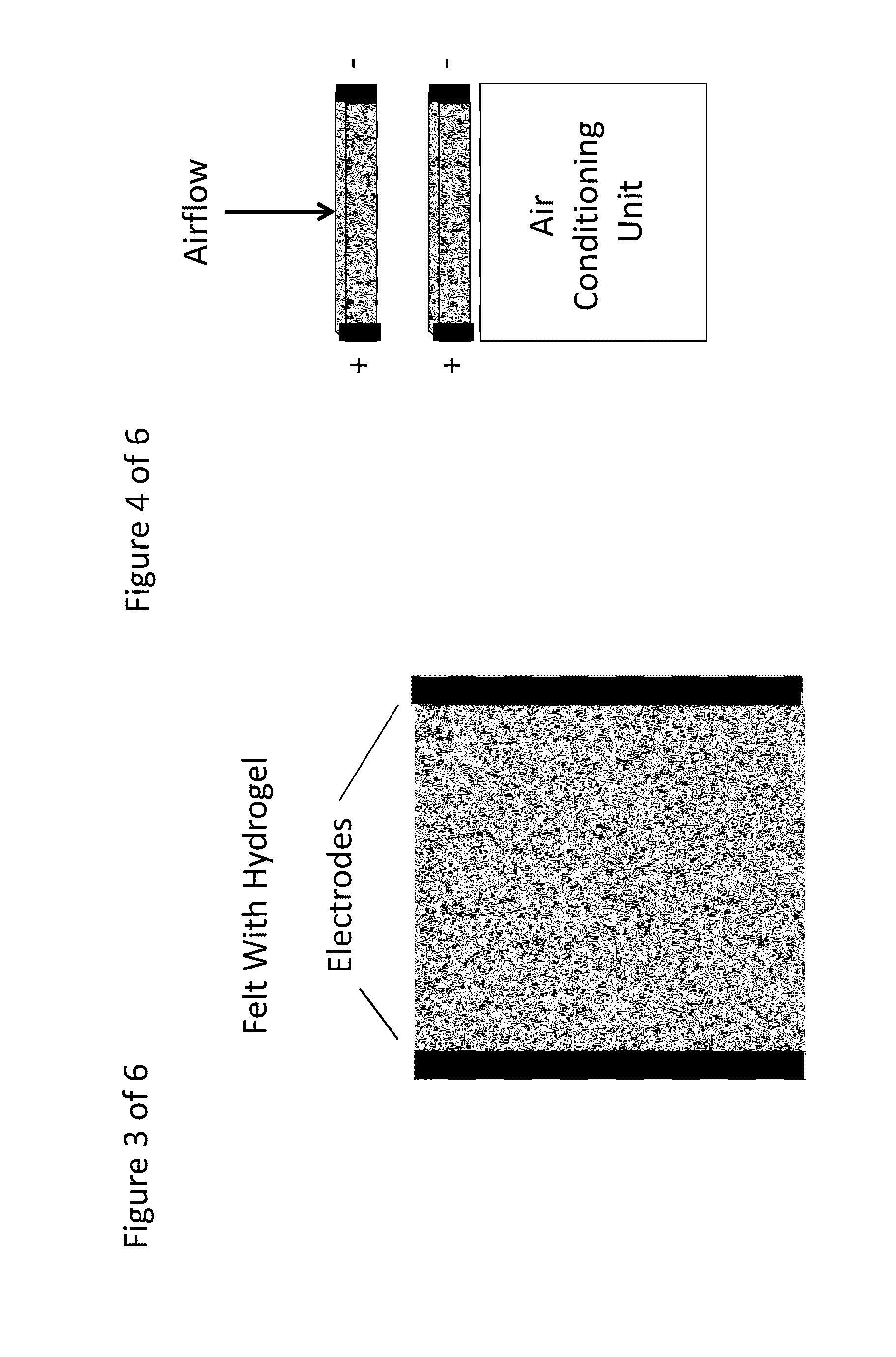
Composite Porous Fibrous Dehumidifying Material
- Summary
- Abstract
- Description
- Claims
- Application Information
AI Technical Summary
Benefits of technology
Problems solved by technology
Method used
Image

Examples
example 1
Comparative
[0059]System: Vapor Compression—
[0060]The most commonly used air conditioning systems:
Qtotal=Qlatent+Qsensible
TABLE I90% RH55% RHLatent Heat EnergyQlatenttoberemoved(BTU)=MassofAir×(Qlatent(in)-Qlatent(out)(In-Out)grainslb.ofDryair×1lbwater7000grains×100lbs.ofDryair×1000BTUslb.ofwaterevaporated ((120 − 54) / 7000) × 100 × 1000 =(70 − 54 / 7000) × 100 × 1000 =943 BTUs229 BTUsof latent heat to be removedof latent heat to be removedSensible Heat Energy To Take Dry Air From 75° F. to 50° F.Qsensible to be removed (BTU) =Mass of Air (lbs.) × (Heat Capacity(in) −Heat Capacity(out)) BTUs / lb. of air ×ΔT (° F.)100 lbs. × (0.24) BTUs / lb.-° F. ×100 lbs. × (0.24) BTUs / lb.-° F. ×25° F. =25° F. =600 BTUs600 BTUsof sensible heat to be removedof sensible heat to be removed
Typical Coefficient Of Performance for vapor compression systems is 3.0, if operating at a coil temperature of 45° F.
TABLE II90% RH55% RHEnergy required to remove heat loadSensible Heat + latent Heat Divided by Coefficient ...
example 2
Comparative
[0061]System: Vapor Compression Air Conditioner Using Desiccant Wheel Dehumidifier—
[0062]System based on zeolites (such as hydrophilic alumina silicates, typically used as desiccants).
[0063]In this system, the latent heat from the phase change of the water vapor to liquid phase is passed on to the dehumidified air, raising its temperature.[0064]1. Exit air temperature from the desiccant=94.2° F.[0065]2. Water Vapor content of exit air=54 grains / lb. of air.[0066]3. Specific Heat Capacity of desiccant=0.22 BTU / lb.-° F.[0067]4. Specific Heat Capacity of air=0.24 BTU / lb.-° F.[0068]5. Heat carryover=latent heat of vaporization of water.[0069]6. Airstream cooled back to input airstream temperature (75° F.), which will require removal of latent heat that was transferred by the desiccant to the dehumidified air.[0070]7. Coil temperature for the vapor compression based cooling system will be at 60° F.
TABLE III90% RH55% RHNo Latent Heat Energy Required As Air Will be Dried By Dessi...
example 3
[0075]System: Vapor Compression Air Conditioner Using Rapid Kinetics Reversible Hydrogel of Present Invention.[0076]Input and output requirements assumed to be same.[0077]Gel absorbs 50% of its weight in water.[0078]2.0 lbs. of gel needed per lb. of water.[0079]Gel Specific Heat Capacity=0.6 BTU / lb.-° F. (measured data)[0080]Gel temperature rise per lb. of water=9° F. (measured)[0081]The carryover heat in this case will be the slight exothermic nature of gel “expansion” when the water vapor deliquesces it.[0082]Cooling by conventional vapor compression remains the same with a COP of 4.0 at a coil temperature of 60° F.
TABLE VI90% RH55% RHNo Latent Heat Energy Required As Air Will be Dried By GelWe will need to provide the energy to cool the air from the inlet to outlet condition, and also provide the energy to cool the slight amount of heat generated due to an exothermic nature of gel expansion.Qsensibletoberemoved(BTU)=[Massairlbs×HeatCapacity(air)BTUs / lbair×ΔTair(°F.)]+Massofgel(lb...
PUM
| Property | Measurement | Unit |
|---|---|---|
| Temperature | aaaaa | aaaaa |
| Temperature | aaaaa | aaaaa |
| Fraction | aaaaa | aaaaa |
Abstract
Description
Claims
Application Information