Driving force transmission device
a transmission device and driving force technology, applied in the direction of friction lining, interengaging clutches, couplings, etc., can solve the problems of poor engagement/release of multi-plate dry clutches, and achieve the effect of reducing drag
- Summary
- Abstract
- Description
- Claims
- Application Information
AI Technical Summary
Benefits of technology
Problems solved by technology
Method used
Image
Examples
first embodiment
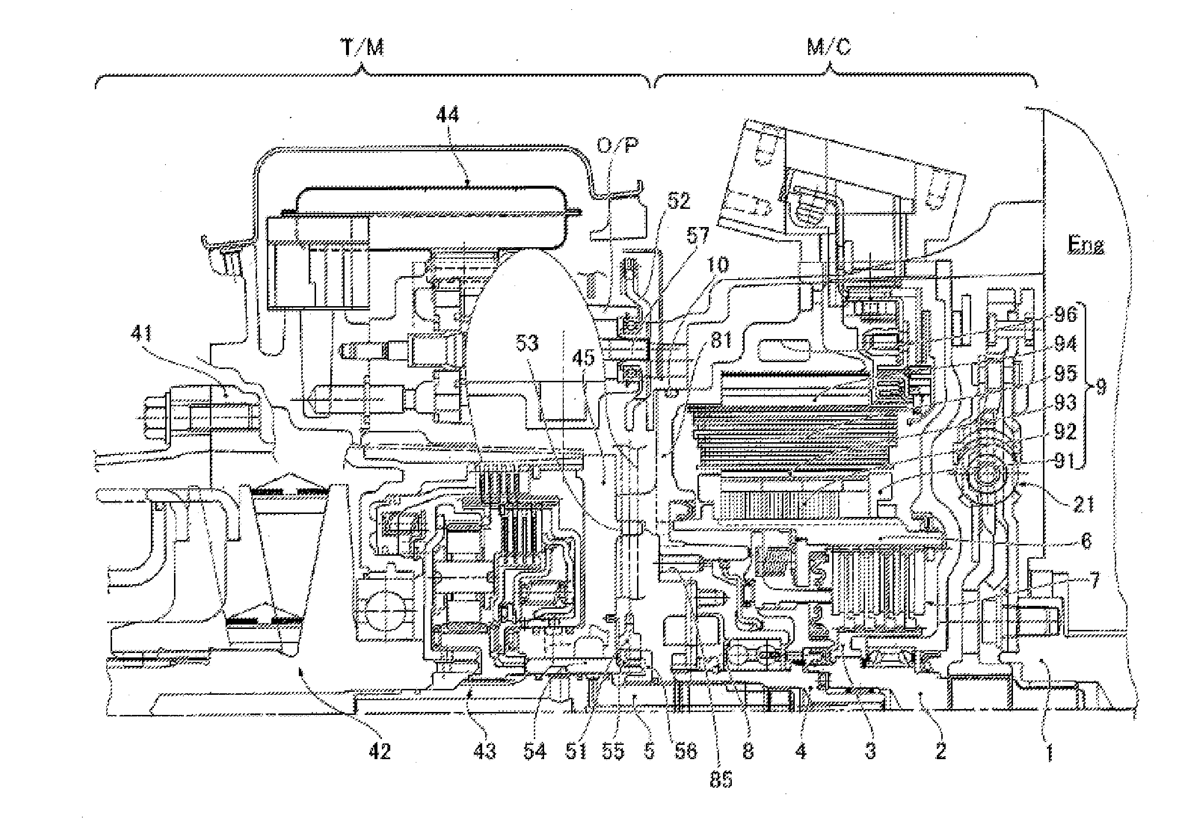
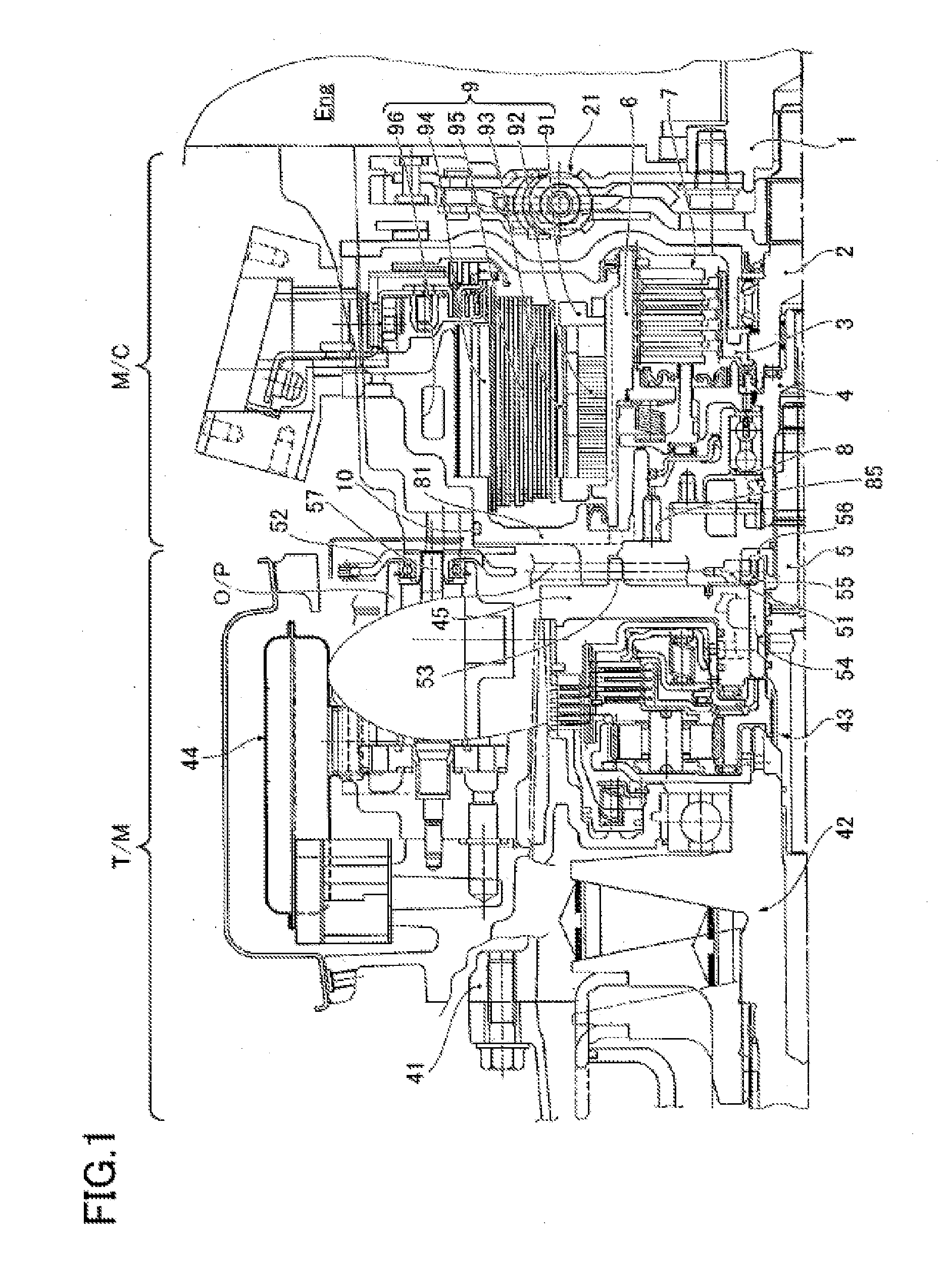
[0021]The hybrid driving force transmission device in the first embodiment has an electric vehicle running mode in which the motor / generator 9 and the transmission input shaft 5 are connected or engaged through the clutch drum 6 and the clutch drum shaft 4 when the multiple-plate dry clutch 7 which is normally in a released state, and a hybrid vehicle running mode in which the engine Eng and the motor / generator 9 are connected through the multiple-plate dry clutch 7 by connecting the engine output shaft 1 and the clutch hub shaft 2 through a damper 21, and the clutch hub 3 and the clutch drum 6 are connected through the engaged (fastened) multiple-plate dry clutch 7.
[0022]The motor and clutch unit M / C includes the multiple-plate dry clutch 7, the slave cylinder 8, and the motor / generator 9. The multiple-plate dry clutch 7 is connected to the engine Eng and configured to connect and disconnect the transmission of a driving force from the engine Eng. The slave cylinder 8 controls the ...
embodiment 1
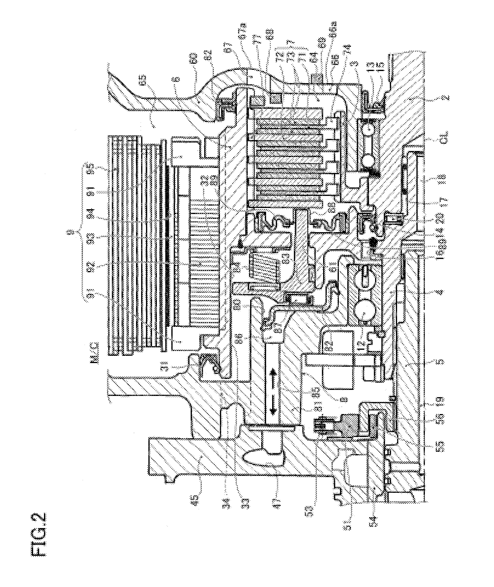
[0036]A bearing lubrication oil passage mechanism in the embodiment 1 includes a needle bearing 20, a second seal member 14, a first shaft center oil passage 19, a second shaft center oil passage 18, a lubrication oil passage 16, and a clearance 17, as shown in FIG. 2. The bearing lubrication oil passage mechanism circulates bearing lubrication oil from the transmission unit T / M to pass the needle bearing 20, the first bearing 12 supporting rotatably the clutch drum 6 on the cylinder housing 81, and the needle bearing 87 disposed between the piston 82 and the piston arm 83, and return to the transmission unit T / M, thereby lubricating the aforementioned bearings.
[0037]The second seal member 14 is disposed between the clutch hub 3 and the clutch drum 6, as shown in FIG. 2. The second seal member 14 is configured to prevent the bearing lubrication oil from flowing from the wet space in which the slave cylinder 8 is disposed into the dry space in which the multiple-plate dry clutch 7 is...
second embodiment
[0080]The friction facing 73 in the second embodiment is provided on both sides of the drive plate 71 and the friction surface is pressed against the plate surface of driven plate 72. This friction facing 73 is an annular plate, and as shown in FIG. 8, and is formed with a facing groove 76′ in such a way that, when D1 is defined as an inner diameter and D2 as an outer diameter, the exit angle β2 to the tangential of the outer diameter is larger than the inflow angle β1 with respect to the tangential of inner diameter with the curve angle being varied gradually from the inflow side toward the outflow side (e.g., trochoid curve).
[0081]Note that other configurations are the same as in the first embodiment, illustration and description thereof is omitted.
[0082]In the second embodiment, the friction facing 73 has a facing groove 76′ in which the exit angle β2 to the tangential to the outer diameter is larger than the inflow angle β1 with respect to the tangential of inner diameter with a...
PUM
 Abstract
Description
Claims
Application Information
 - R&D
- Intellectual Property
- Life Sciences
- Materials
- Tech Scout
- Unparalleled Data Quality
- Higher Quality Content
- 60% Fewer Hallucinations
Browse by: Latest US Patents, China's latest patents, Technical Efficacy Thesaurus, Application Domain, Technology Topic, Popular Technical Reports.
© 2025 PatSnap. All rights reserved.Legal|Privacy policy|Modern Slavery Act Transparency Statement|Sitemap|About US| Contact US: help@patsnap.com


