Shear wave velocity estimation using center of mass

a technology of center mass and shear wave velocity, applied in applications, ultrasonic/sonic/infrasonic image/data processing, ultrasonic/sonic/infrasonic diagnostics, etc., can solve the problems of simple detection, location by location, and inability to determine group velocity, and achieve low signal-to-noise ratio (snr) and increase the effect of accuracy

Active Publication Date: 2013-11-28
KONINKLIJKE PHILIPS ELECTRONICS NV
View PDF3 Cites 27 Cited by
  • Summary
  • Abstract
  • Description
  • Claims
  • Application Information

AI Technical Summary

Benefits of technology

[0017]Alternatively or in addition, lateral locations can likewise be selectively excluded based on sufficiently low displacement. The low displacement, in either case, can allow noise to assume a greater adverse impact. Accordingly, low signal-to-noise ratio (SNR) data is filtered out of the wave-arrival time computation, thereby increasing its accuracy.

Problems solved by technology

Therefore, simply detecting, location by location, when a fixed displacement is achieved, is not a feasible means for determining group velocity.

Method used


Image

  • Shear wave velocity estimation using center of mass
  • Shear wave velocity estimation using center of mass
  • Shear wave velocity estimation using center of mass

Examples


Embodiment Construction

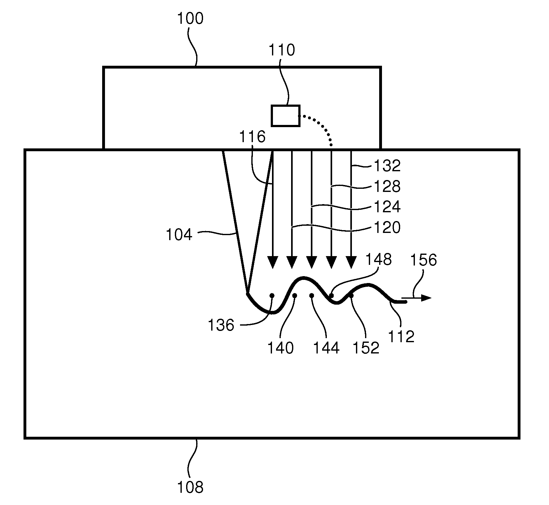
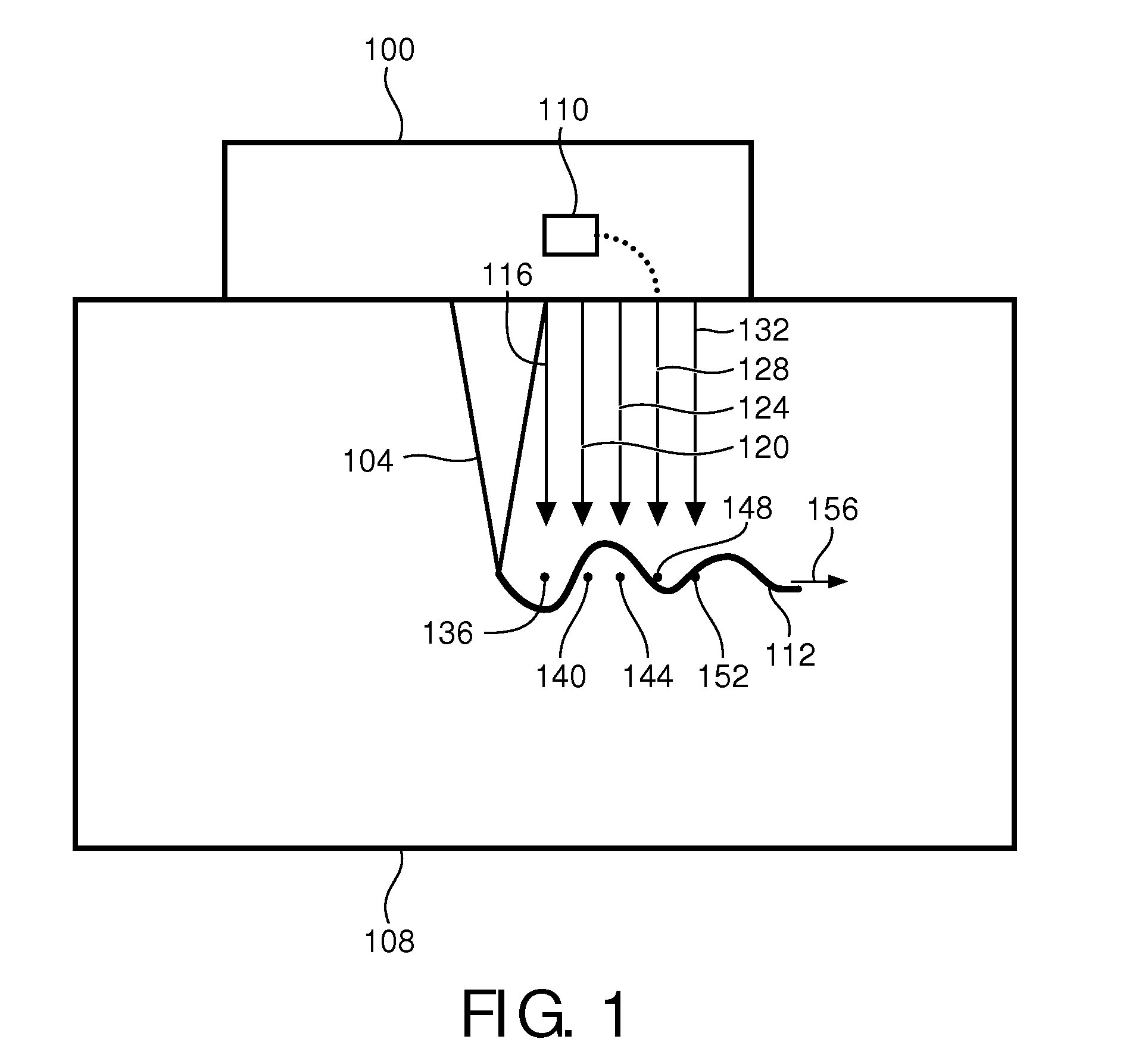
[0045]FIG. 1 is an example of an ultrasound probe 100 comprising an ultrasound transducer (not shown) firing a pushing beam 104 into a medium 108 such as body tissue. In particular, high intensity, narrow bandwidth signals are fired with a repetition rate of, for example, 100 Hz. The probe 100 includes an in-place, displacement-based weighter 110.

[0046]The resulting pushing beams 104 each cause a respective shear wave 112. Responsively, tracking beams 116, 120, 124, 128, 132 issue from the ultrasound probe 100, and their respective echoes (not shown) are received for processing.

[0047]The tracking beams 116-132 are utilized to measure shear-wave-induced vertical displacement in the body tissue 108 at different spatial locations 136, 140, 144, 148, 152 along a path 156 of the shear wave 112. Initially, reference pulses (not shown) are issued to each of the locations to provide a frame of reference for subsequent measurement of the displacement.

[0048]The shear wave 112 travels through ...


PUM


Abstract

The weighted-average-based position (244) in the temporal domain is computed based on the sampling of shear wave displacement (226) along the propagation path. The weighting is, for example, by displacement observed at times (230) corresponding to sampling and represents the time of arrival of the shear wave at the shear-wave propagation path location being sampled. In some embodiments, the computed shear-wave times of arrival at respective locations are functionally related to known inter-location distances (250) to derive shear-wave group velocity. The derived velocity can serve as input into known algorithms for estimating shear elasticity of the medium, such as body tissue, for purposes of clinical diagnosis and therapy assessment.

Description

FIELD OF THE INVENTION[0001]The present invention is directed to detecting shear-wave time-of-arrival and, more particularly, to doing so based on shear-wave-induced displacement.BACKGROUND OF THE INVENTION[0002]Mechanical changes in living tissue correlate with pathological changes. As between healthy and pathological tissue, the shear elastic modulus (stiffness) and viscosity can vary significantly. With the advent of ultrasound elasticity imaging development over the past decade, many clinical studies have shown that tissue visco-elastic properties provide useful information to physicians for better cancer diagnosis and therapy assessment.[0003]One method for measuring tissue mechanical properties is ultrasound shear wave elastography. It utilizes acoustic radiation force (ARF) to generate shear waves in soft tissue and subsequently tracks shear wave displacement to estimate tissue elasticity and viscosity. An application of this technique is the non-invasive measurement of liver...

Claims


Application Information

Patent Timeline
Patent Type & Authority Applications(United States)
IPC IPC(8): A61B8/08A61B8/00
CPCA61B8/485A61B8/4483A61B8/5207A61B5/0051A61B5/055A61B5/4244A61B5/7235A61B2562/0204
Inventor SHI, YANXIE, HUAPETERSON, ROYROBERT, JEAN-LUCSHAMDASANI, VIJAY
Owner KONINKLIJKE PHILIPS ELECTRONICS NV
Why Eureka
Try Eureka