

Method and apparatus for resetting valve lift for use in engine brake
- Summary
- Abstract
- Description
- Claims
- Application Information
AI Technical Summary
Benefits of technology
Problems solved by technology
Method used
Image

Examples
first embodiment
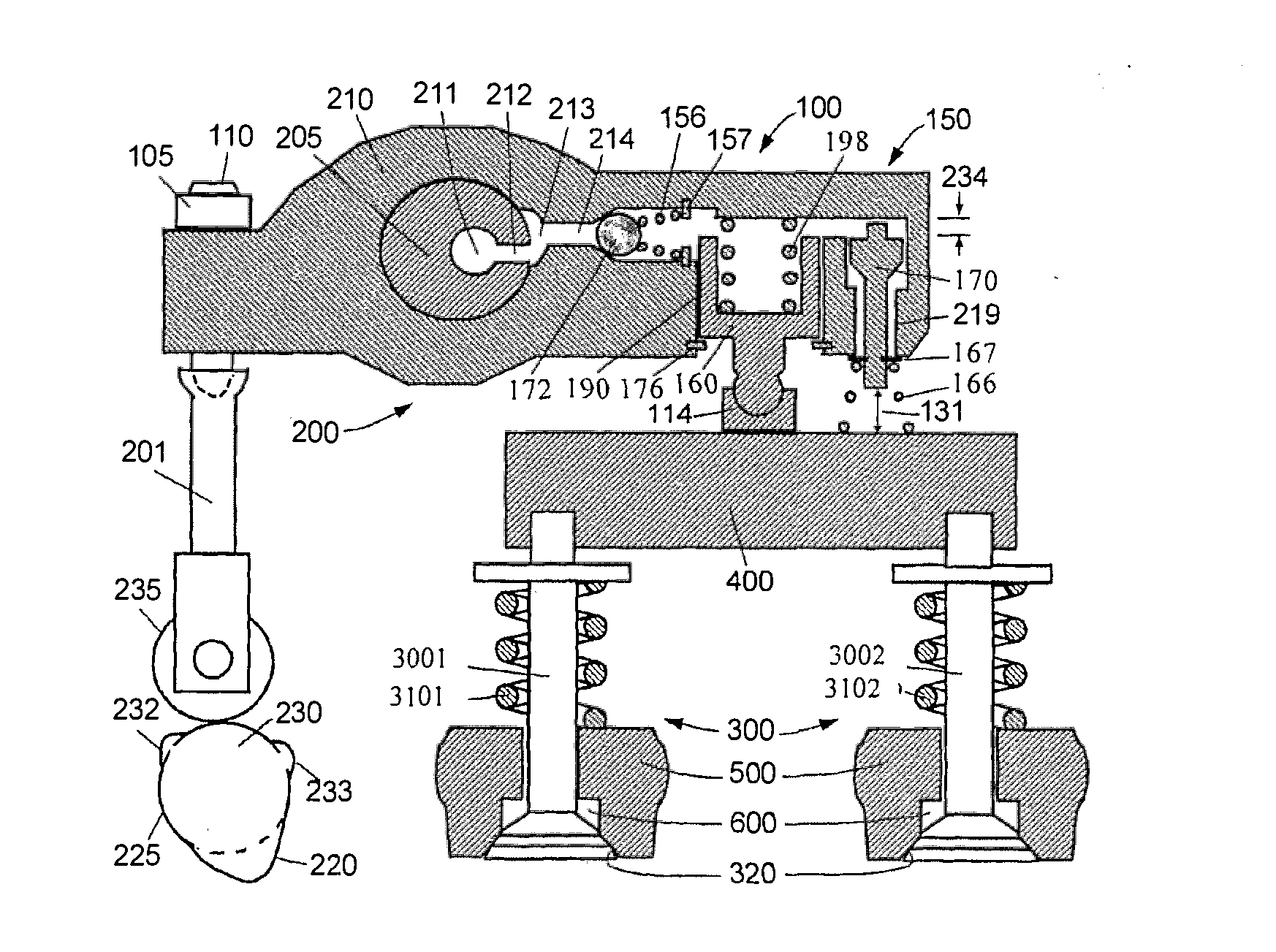
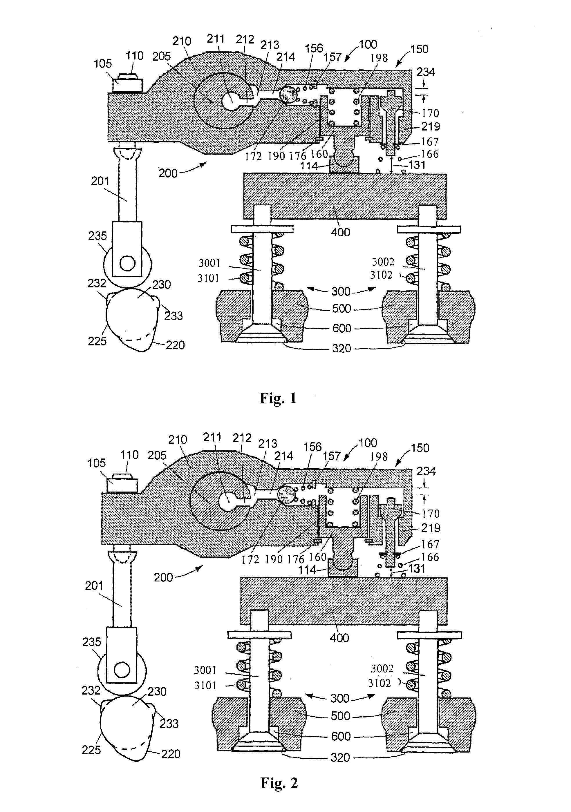
[0047]Reference is made to FIGS. 1 and 2, which are schematic diagrams showing a first embodiment of the present application when the engine brake is at the “OFF” and “ON” positions respectively. There are four main parts in FIGS. 1 and 2, including an exhaust valve actuator 200, an exhaust valve 300 (including an exhaust valve 3001 and an exhaust valve 3002), an engine brake actuation mechanism 100 and a valve lift reset mechanism 150.
[0048]The exhaust valve actuator 200 includes a cam 230, a cam follower 235, a push rod or a push tube 201 (overhead cam engine does not need the push rod or the push tube 201), a rocker arm 210 and a valve bridge 400 (an engine with one valve per cylinder does not need the valve bridge 400). Generally a valve lash adjusting system is arranged at one end of the rocker arm 210 (one end close to the valve bridge or one end close to the push rod). In the present embodiment, a valve lash adjusting screw 110 and the push rod 201 are connected to form the v...
second embodiment
[0059]Reference is made to FIGS. 6 and 7, which are schematic diagrams showing a valve reset mechanism for an engine brake according to a second embodiment of the present application when the engine brake is at the “OFF” and “ON” positions respectively. The major difference between the present embodiment and the first embodiment is that the valve lift reset mechanism 150 in the rocker arm 210 is moved from an outer end close to the braking piston 160 to an inner end between the braking piston 160 and the rocker arm shaft 205. In addition, the reset valve is changed from a lifting-type plunger valve in the first embodiment to a sliding-type plunger valve in the present embodiment.
[0060]When the engine braking is required, the brake control mechanism is turned on and the solenoid valve 51 supplies oil to the brake actuation mechanism 100 through the brake fluid network. Oil pressure overcomes the force of the spring 166 and pushes the reset piston 170 downward from the oil-draining po...
third embodiment
[0063]Reference is made to FIGS. 8 and 9, which are schematic diagrams showing a valve reset mechanism according to a third embodiment of the present application when the engine brake is at the “OFF” and “ON” positions respectively. An overhead cam engine is provided in the present application, thus there is no push rod or push tube, and the exhaust valve lash adjusting screw 110 is mounted on a side close to the valve bridge 400. The brake actuation mechanism 100 is integrated in the valve bridge 400. The braking piston 160 is placed in a piston bore 190 which is an upward opening in the center of the valve bridge 400. A preload spring 198 provided between the braking piston 160 and the valve bridge 400 biases the braking piston 160 upward against the elephant foot pad 114. A one-way valve 172 is placed in the braking piston 160.
[0064]A reset valve of the valve lift reset mechanism 150 is also located between the rocker arm 210 and the valve bridge 400, and includes a reset piston ...
PUM
 Abstract
Description
Claims
Application Information