Motor driving circuit and electronic apparatus using the same

Active Publication Date: 2013-12-05
ROHM CO LTD
View PDF5 Cites 5 Cited by
  • Summary
  • Abstract
  • Description
  • Claims
  • Application Information

AI Technical Summary

Benefits of technology

[0006]The present disclosure provides various embodiments of a mo

Problems solved by technology

Specifically, it has been found that, even when the switching frequency is set to the out-of audible band, an effective frequency of the pulsed drivi

Method used


Image

  • Motor driving circuit and electronic apparatus using the same
  • Motor driving circuit and electronic apparatus using the same
  • Motor driving circuit and electronic apparatus using the same

Examples


Example

First Embodiment

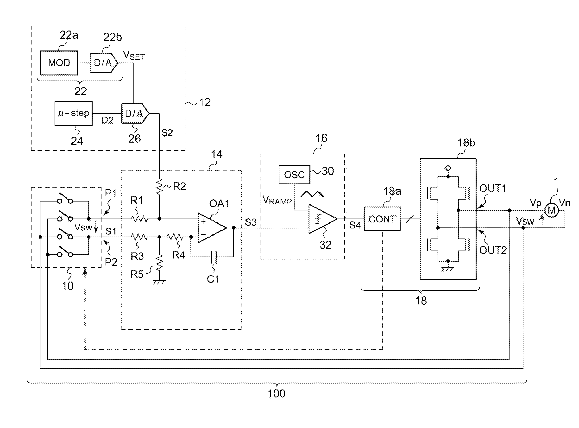
[0042]FIG. 1 is a circuit diagram of a motor driving circuit 100 according to a first embodiment of the present disclosure. The motor driving circuit 100 supplies a switching voltage Vsw to a motor 1. The motor 1 may be any kind of suitable motor or similarly structured devices, including a linear actuator (such as a voice coil motor (VCM)), a spindle motor, a stepping motor and so on. The motor driving circuit 100 shown in FIG. 1 performs a feedback control of a state of the motor 1 based on an effective value of the switching voltage Vsw supplied to the motor 1.

[0043]The motor driving circuit 100 includes a detecting circuit 10, a command value generating unit 12, an error amplifier 14, a pulse width modulator 16 and an output circuit 18.

[0044]The motor driving circuit 100 generates a detection signal S1 indicating a current state of the motor 1. In this embodiment, the detection signal S1 is the switching voltage Vsw supplied to the motor 1. The detection signal S...

Example

Second Embodiment

[0068]In a second embodiment of the present disclosure, an audible noise is further reduced by controlling a time constant (or band) of a feedback loop including the error amplifier 14, in addition to providing a variation to the command value S2.

[0069]FIG. 4 is a circuit diagram of a motor driving circuit 100a according to the second embodiment. The time constant of the feedback loop can be changed by configuring a first capacitor C1, which is a feedback capacitor, as a variable capacitor and / or configuring a fourth resistor R4 as a variable resistor. In FIG. 4, the capacitor C1 has a variable capacitance and a time constant controller 34 changes the capacitance of the first capacitor C1.

[0070]The time constant controller 34 monitors the digital value D2 representing the command value S2 and sets the time constant to be longer, in other word, narrows a band of the feedback loop if the digital value D2 remains constant for a predetermined detection period τ. In a no...

Example

Third Embodiment

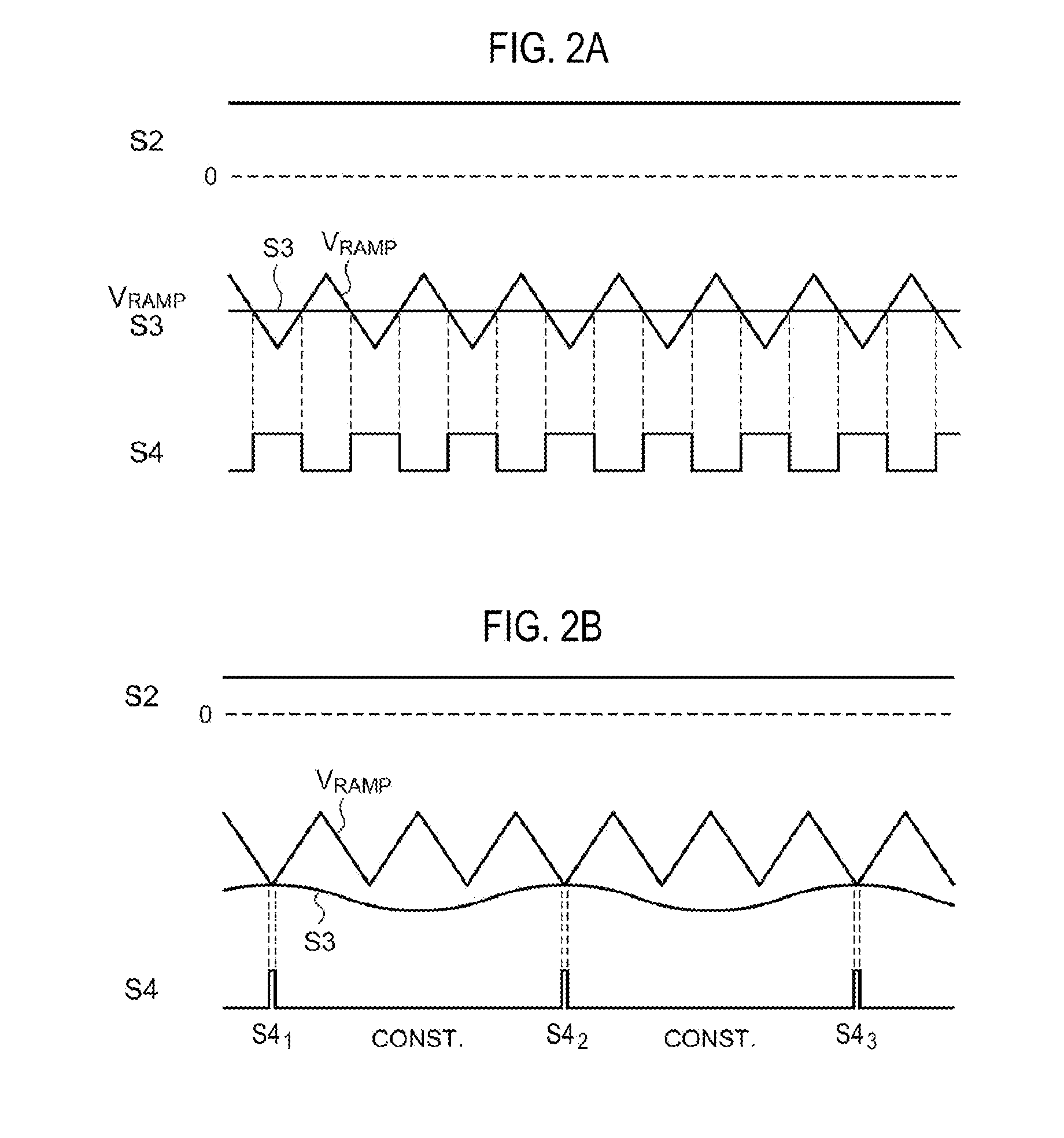
[0075]In a third embodiment, a periodic or random variation may be applied to a voltage range (bottom voltage) of the ramp signal VRAMP generated by an oscillator 30 in addition to or as an alternative to varying the command value S2. This allows variation of time at which the error signal S3 crosses the ramp signal VRAMP in the waveform diagram of FIG. 2C, which may result in a spread spectrum.


PUM


Abstract

A motor driving circuit for driving a motor, includes: a detecting circuit configured to detect a detection signal indicative of a current state of the motor; a command value generating unit configured to generate a command value indicative of a target state of the motor; an error amplifier configured to generate an error signal by amplifying an error between the detection signal and the command value; a pulse width modulator configured to generate a pulse signal; and an output circuit. The command value generating unit is configured to provide a variation to the command value.

Description

CROSS-REFERENCE TO RELATED APPLICATION[0001]This application is based upon and claims the benefit of priority from Japanese Patent Application No. 2012-128254, filed on Jun. 5, 2012, the entire contents of which are incorporated herein by reference.TECHNICAL FIELD[0002]The present disclosure relates to a motor driving circuit for switch-driving a motor.BACKGROUND[0003]A voice coil motor, a spindle motor or a stepping motor is used to position or rotate an object. A motor driving circuit adjusts power supplied to a motor through a feedback control such that a detecting signal indicating a current state of the motor reaches a command value indicating a target state of the motor.[0004]Such a motor driving scheme may be generally classified into a linear driving type and a switching driving type. For the switch-driving type, a pulsed driving voltage having a switching frequency is supplied to a motor. In the motor driving circuit, the switching frequency is frequently set to an out-of a...

Claims


Application Information

Patent Timeline
IPC IPC(8): H02P29/00H02P29/02H02P23/04
CPCH02P29/00H02P7/29H02P29/50B25B23/1405B25B23/1453F16P3/08G01R15/18
Inventor SUGIE, HISASHI
Owner ROHM CO LTD
Why Eureka
Try Eureka