
Passive radar device

Inactive Publication Date: 2013-12-05
MITSUBISHI ELECTRIC CORP
View PDF5 Cites 10 Cited by
  • Summary
  • Abstract
  • Description
  • Claims
  • Application Information

AI Technical Summary

Benefits of technology

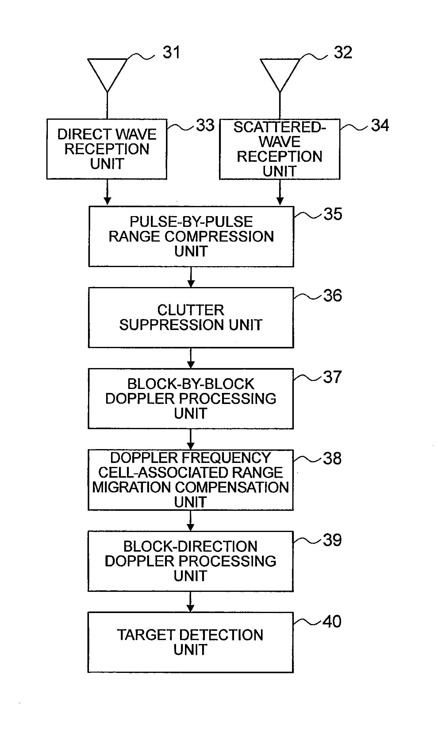
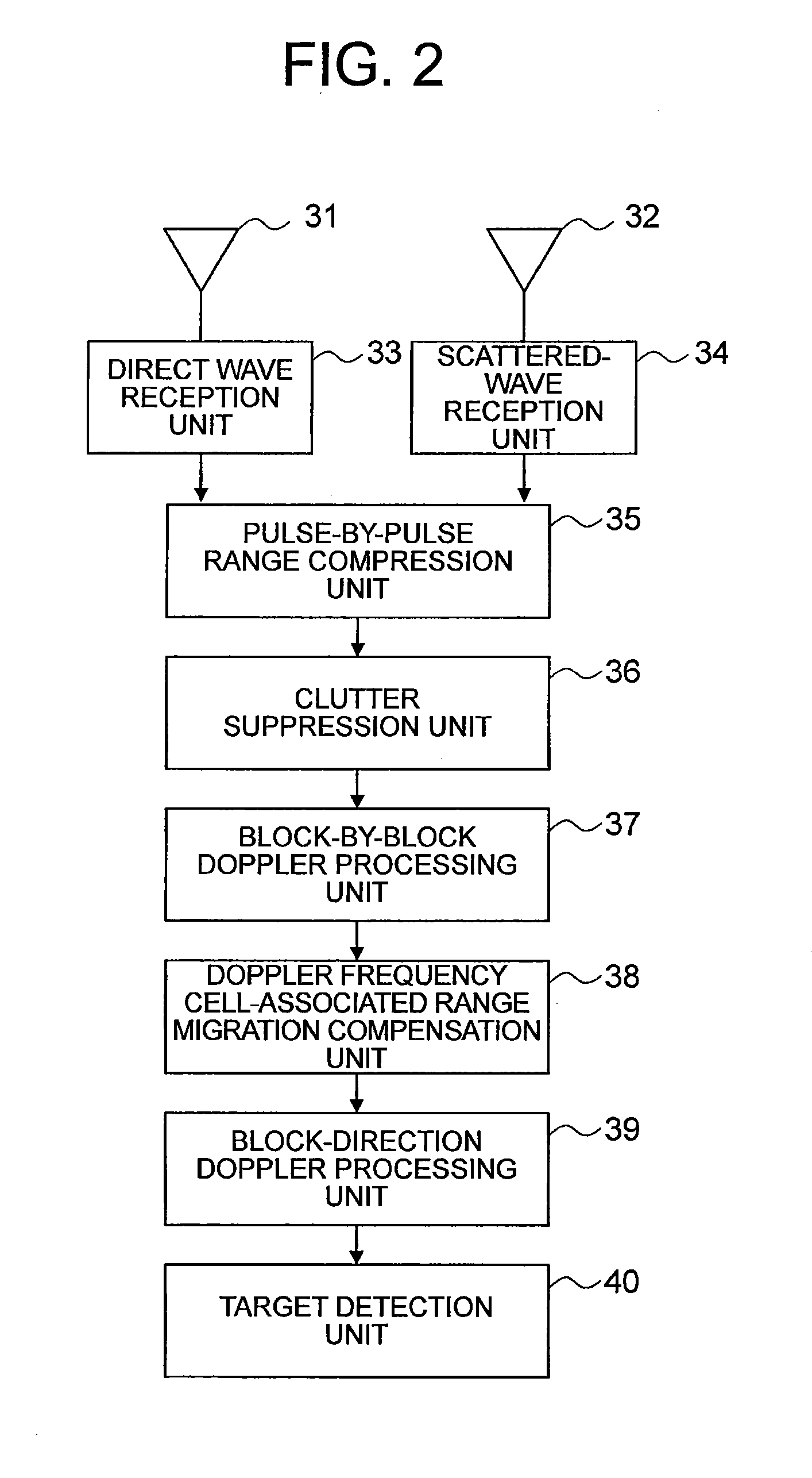
The present invention provides a passive radar device that can extend the observing time and improve signal-to-noise ratio (SNR) while stretching detection range. This is achieved by a pulse-by-pulse range compression unit, a block-by-block Doppler processing unit, a Doppler frequency cell-associated range migration compensation unit, and a block-direction Doppler processing unit. The device can accurately track the movement of a target by dividing data into short pulses and performing long-period correlation processing between a direct wave and a scattered wave.

Problems solved by technology

The reason that it is particularly difficult to stretch the detection range with the passive radar system is because power of the radio wave transmitted from the radio source is feeble compared to a detection radar such as a conventional active system, which extremely lowers a signal to noise ratio (SNR).
However, by extending the integration time, the target moves between range cells during an observing time, which causes a problem in that there is a change in a distance from a target signal and a Doppler frequency thereof, but Patent Literatures 1 to 3 each disclose a countermeasure against this problem.

Method used


Image

  • Passive radar device
  • Passive radar device
  • Passive radar device

Examples


first embodiment

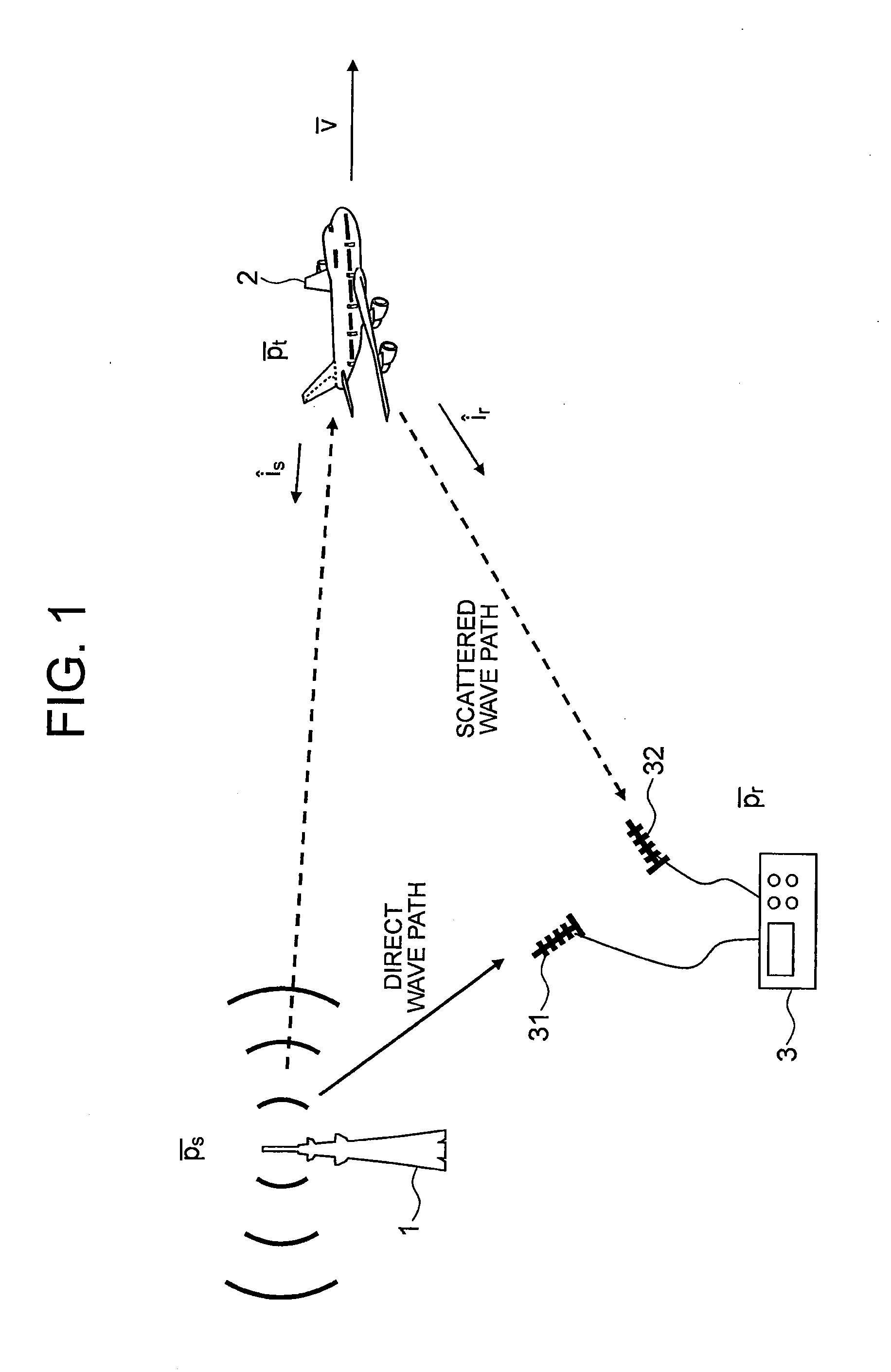
[0036]FIG. 1 is an explanatory diagram illustrating a concept of a passive radar along with a geometry of observation. In FIG. 1, a radio wave transmitted from a broadcasting station 1 being a radio source is received by an antenna 31 for direct-wave reception and an antenna 32 for scattered-wave reception that are provided to a receiving station 3.

[0037]Here, the antenna 31 for direct-wave reception is disposed so as to be directed toward the broadcasting station 1, and receives a radio wave (direct wave) that directly arrives after being transmitted from the broadcasting station 1. Further, the antenna 32 for scattered-wave reception is disposed so as to be directed toward an observed area in which a target 2 exists, and receives a radio wave (scattered wave) that has been transmitted from the broadcasting station 1 and scattered by the target 2.

[0038]It is assumed that the broadcasting station 1 is continuously transmitting (broadcasting) a signal having a carrier frequency fc an...

second embodiment

[0116]FIG. 7 is a block diagram illustrating a passive radar device according to a second embodiment of the present invention. In FIG. 7, the passive radar device includes the antenna 31 for direct-wave reception, the antenna 32 for scattered-wave reception, the direct-wave reception unit 33, the scattered-wave reception unit 34, the pulse-by-pulse FFT unit 35a, the pulse-by-pulse FFT unit 35b, the complex conjugate multiplication unit 35c, the clutter suppression unit 36, the block-by-block Doppler processing unit 37, the phase function 38b for range migration compensation, the multiplication unit 38c, the IFFT unit 38d, the block-direction Doppler processing unit 39, and the target detection unit 40.

[0117]Here, the pulse-by-pulse FFT unit 35a, the pulse-by-pulse FFT unit 35b, and the complex conjugate multiplication unit 35c, and the phase function 38b for range migration compensation, the multiplication unit 38c, and the IFFT unit 38d are the same as those illustrated in FIGS. 4 ...

third embodiment

[0123]FIG. 8 is a block diagram illustrating a passive radar device according to a third embodiment of the present invention. In FIG. 8, the passive radar device further includes a block signal addition unit 41 in addition to the components of the passive radar device illustrated in FIG. 7. The other components are the same as those of the second embodiment described above, and hence descriptions thereof are omitted.

[0124]FIG. 9 is an explanatory diagram illustrating handling of a received signal in processing performed by the passive radar device according to the third embodiment of the present invention. FIG. 9 is substantially the same as FIG. 3, and hence a description is made of only different points from FIG. 3.

[0125]In FIG. 3, the blocks are set so that the adjacent blocks do not overlap each other, while in FIG. 9, the adjacent blocks overlap each other. For example, in FIG. 3, the pulses forming the second block have the pulse numbers of N to 2N−1, while in FIG. 9, the puls...


PUM


Abstract

A passive radar device includes: a pulse-by-pulse range compression unit executing cross-correlation processing between received signals of a direct wave and scattered wave on each of pulses divided by a direct-wave reception unit and a scattered-wave reception unit, and calculating a pulse-by-pulse range profile; a block-by-block Doppler processing unit calculating a first Doppler frequency spectrum by executing pulse-direction Fourier transform in block units each grouping plural pulses; a Doppler frequency cell-associated range migration compensation unit compensating a range-direction movement amount with respect to the first Doppler frequency spectrum on a Doppler-frequency-cell-by-Doppler-frequency-cell basis and on a block-by-block basis; and a block-direction Doppler processing unit calculating a second Doppler frequency spectrum by executing block-direction Fourier transform on an output from the Doppler frequency cell-associated range migration compensation unit.

Description

TECHNICAL FIELD [0001]The present invention relates to a passive radar device that uses a radio wave transmitted from an existing radio source to detect an azimuth of a target, a distance therefrom, and the like based on a signal that directly arrives from the radio source and a signal scattered by the target.BACKGROUND ART [0002]A passive radar device is a device that uses a radio wave transmitted from an existing radio source such as a broadcasting station to detect an azimuth of a target, a distance therefrom, and the like by measuring a path length difference between a signal (direct wave) that directly arrives from the radio source and a signal (scattered wave) scattered by the target and a Doppler frequency shift of a scattered-wave signal.[0003]Here, examples considered as the radio source include a global navigation satellite system (GNSS) in addition to a television or radio broadcasting station. A passive radar is attracting attention as a system useful for power saving an...

Claims


Application Information

Patent Timeline
IPC IPC(8): G01S7/285
CPCG01S7/285G01S13/46G01S13/878G01S13/5244G01S13/5246
Inventor SUWA, KEIOSHIMA, TADASHINAKAMURA, SHOHEIWAKAYAMA, TOSHIO
Owner MITSUBISHI ELECTRIC CORP
Learn More