Engine and piston

a technology of engine and piston, applied in the direction of machines/engines, mechanical equipment, heat inorganic powder coating, etc., can solve the problem of limiting the improvement of engine fuel efficiency, and achieve the effect of improving engine fuel efficiency, high heat insulation, and high surface smoothness

Inactive Publication Date: 2013-12-12
AISIN SEIKI KK +1
View PDF1 Cites 20 Cited by
  • Summary
  • Abstract
  • Description
  • Claims
  • Application Information

AI Technical Summary

Benefits of technology

[0019]According to the invention, employment of the heat insulating coating having high heat insulation and high surface smoothness improves heat insulation of the combustion chamber and contributes to improvement of fuel efficiency of the engine. Furthermore, because the surface smoothness of the top of the piston can be increased, it is possible to suppress knocking of the engine.
[0020]According to the invention, because the heat insulation of the combustion chamber of the engine can be improved as described above, thermal efficiency of the engine at the time of cold start is improved and the fuel efficiency of the engine is improved. In general, at the time of the cold start of the engine, fuel is not vaporized well and therefore a larger amount of fuel (such as gasoline) than usual is sent into the combustion chamber. However, if the heat insulating coating according to the invention is provided, it is possible to effectively carry out heat insulation of the combustion chamber of the engine to thereby improve vaporization of the fuel to improve the fuel efficiency. Especially in hybrid vehicles and idling stop vehicles which are increasing in number in recent years, the engine is not sufficiently warmed up due to intermittent operation of the engine. In this case, the heat insulating coating according to the invention exerts the effect and it is easy to maintain the combustion chamber of the engine at high temperature. Moreover, because combustion heat in the combustion chamber is less liable to escape into the piston, the cylinder block, the cylinder head, and the like, combustion temperature in the combustion chamber increases and an effect on reduction of HC (hydrocarbon) included in exhaust gas can be expected as well.

Problems solved by technology

In these cases, because a temperature of the combustion chamber in the engine is likely to reduce, there is a limit on the improvement of the fuel efficiency of the engine.

Method used


Image

  • Engine and piston
  • Engine and piston
  • Engine and piston

Examples


first embodiment

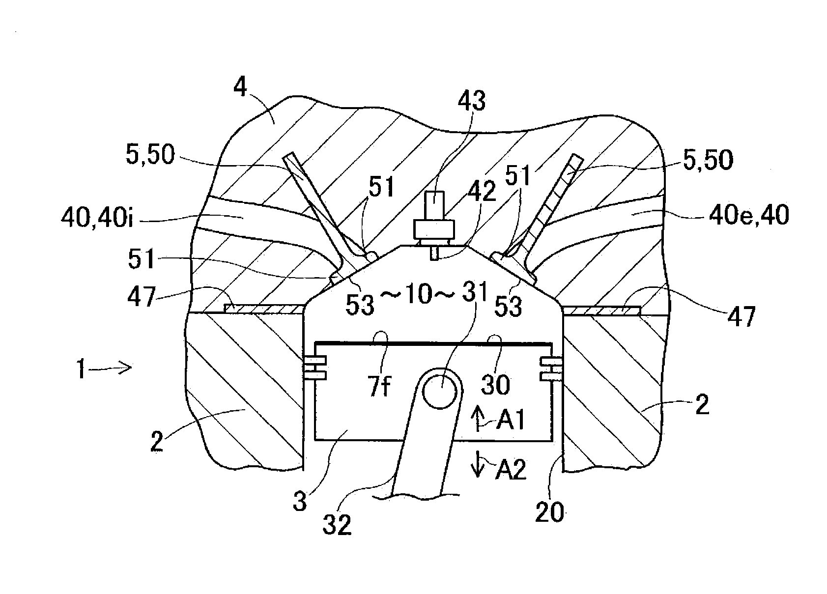
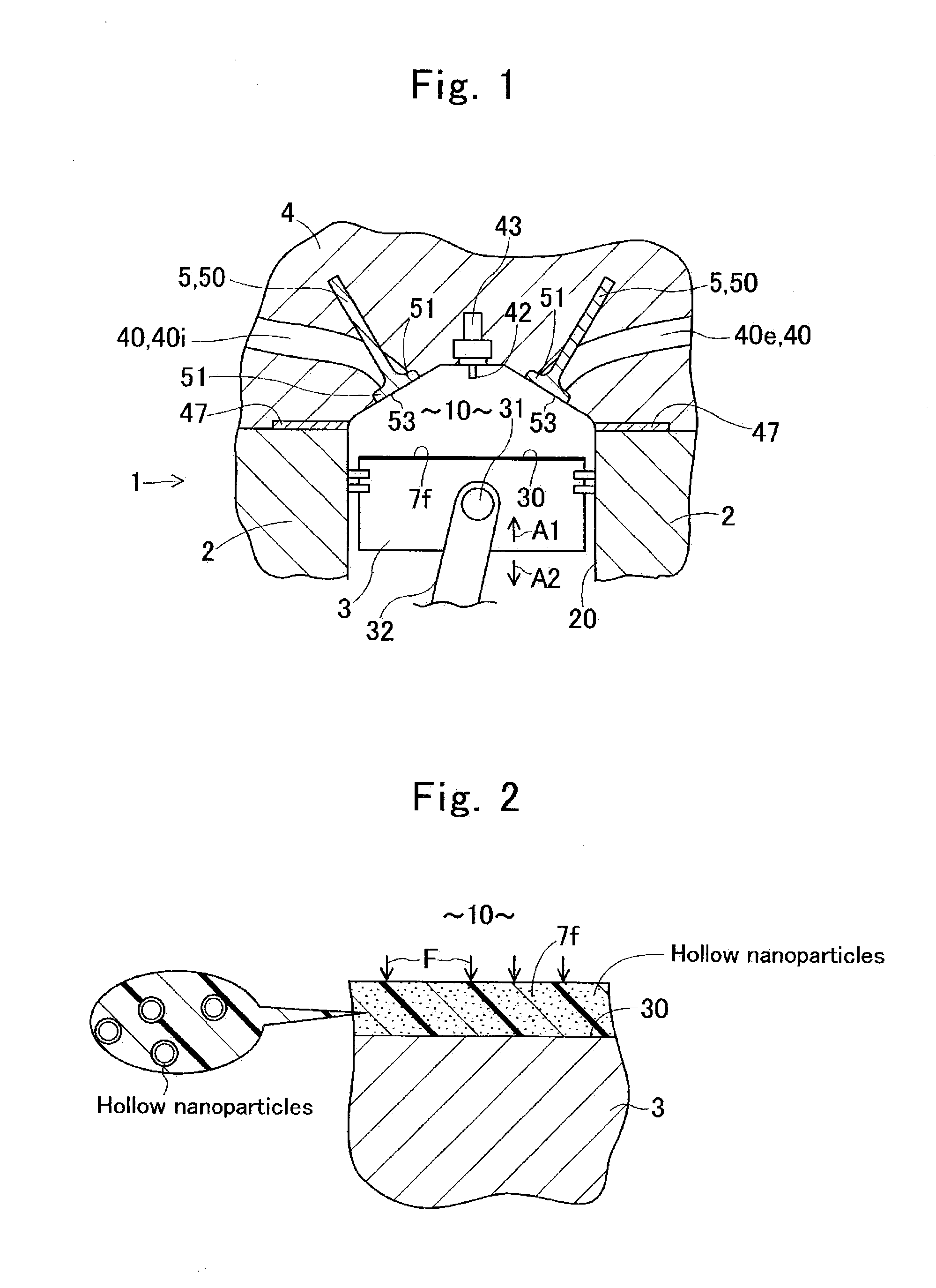
[0039]FIGS. 1 and 2 schematically show a concept of a first embodiment. FIG. 1 schematically shows a section near a combustion chamber 10 of an engine 1. The engine 1 is a piston-type internal combustion engine. FIGS. 1 and 2 are merely conceptual sketches and not intended to specify the details. The engine 1 includes a cylinder block 2 having a bore 20, a piston 3 fitted into the bore 20 so as to form the combustion chamber 10 on a top 30 side and to be able to reciprocate in directions of arrows A1 and A2, a cylinder head 4 for closing the combustion chamber 10 and having valve bores 40 communicating with the combustion chamber 10, and valves 5 for opening and closing the valve bores 40. The valve bores 40 include an intake valve bore 40i and an exhaust valve bore 40e which can communicate with the combustion chamber 10. The cylinder head 4 is mounted to the cylinder block 2 with a gasket 47 interposed therebetween. The cylinder block 2, the cylinder head 4, and the piston 3 are m...

second embodiment

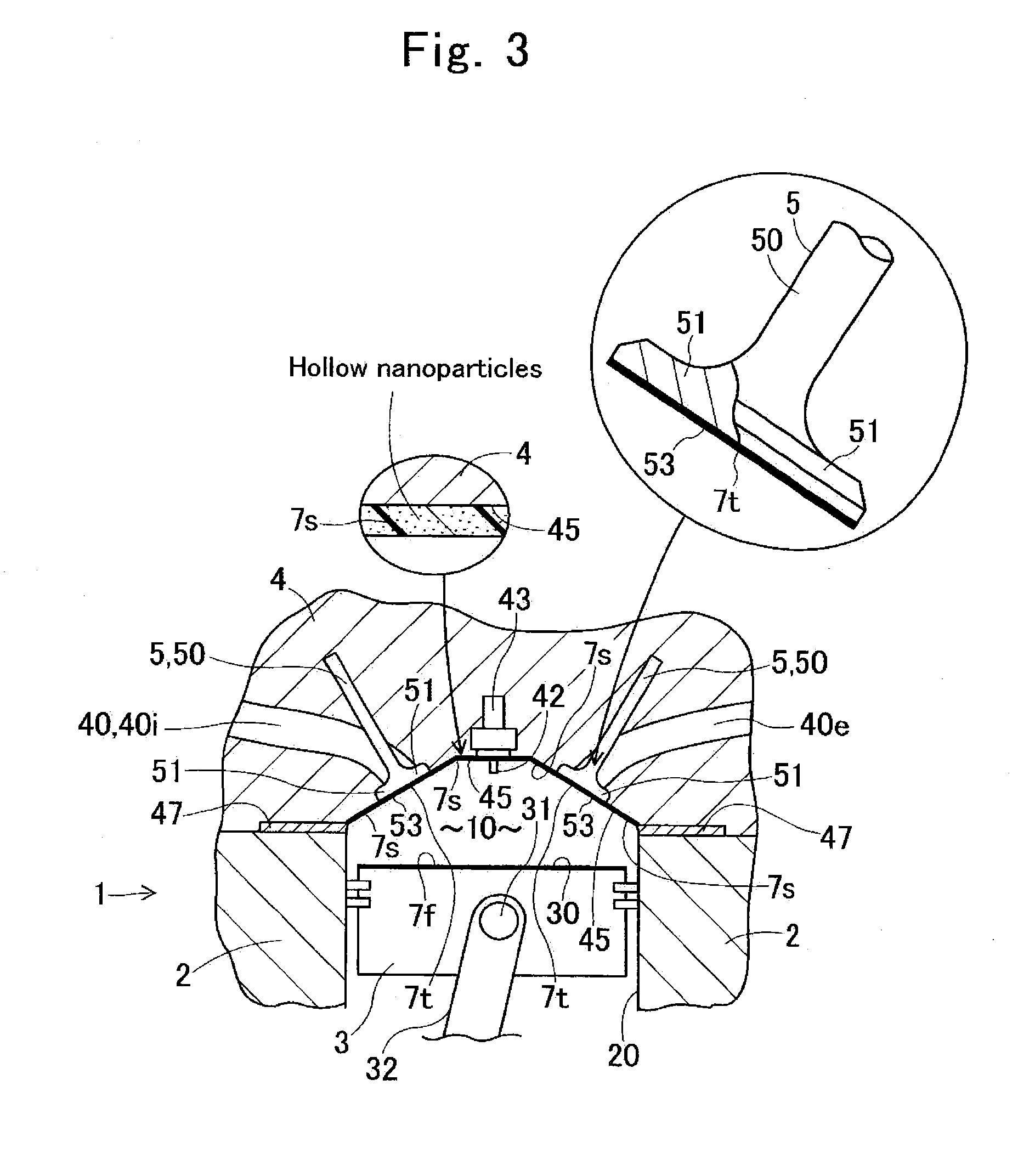
[0048]FIG. 3 shows a second embodiment. The present embodiment has basically the same structure, operation, and effects as the first embodiment. FIG. 3 schematically shows a section near a combustion chamber 10 of an engine 10. A first heat insulating coating 7f is applied on a top 30 which is a wall face of the piston 3 and facing the combustion chamber 10. Moreover, a second heat insulating coating 7s is applied on a wall face 45 of a cylinder head 4 and facing the combustion chamber 10. Because the first heat insulating coating 7f and the second heat insulating coating 7s are formed, heat insulation of the combustion chamber 10 is improved. Depending on circumstances, if the second heat insulating coating 7s is formed on the wall face 45 of the cylinder head 4, the first heat insulating coating 7f may be omitted. Surface roughness of the wall faces after the application of the heat insulating coatings 7f and 7s is smaller than surface roughness before the application.

third embodiment

[0049]The present embodiment has basically the same structure and effects as the first and second embodiments and therefore FIGS. 1 to 3 can be used with modifications. A first heat insulating coating 7f is applied on a top 30 which is a wall face of a piston 3 and facing a combustion chamber 10. Furthermore, a second heat insulating coating 7s is applied on a wall face 45 of the cylinder head 4 and facing the combustion chamber 10. In addition, a third heat insulating coating 7t is formed on a valve face 53 of each of valves 5 and facing the combustion chamber 10. In this manner, the first heat insulating coating 7f is formed on the top 30 of the piston 3, the second heat insulating coating 7s is formed on the wall face 45 of the cylinder head 4 and facing the combustion chamber 10, and the third heat insulating coating 7t is formed on the valve face 53 of each of the valves 5 and facing the combustion chamber 10. Therefore, heat insulation of the combustion chamber 10 is further i...


PUM

PropertyMeasurementUnit
thicknessaaaaaaaaaa
sizeaaaaaaaaaa
sizeaaaaaaaaaa

Abstract

An engine includes a cylinder block having a bore, a piston fitted into the bore so as to form a combustion chamber and to be able to reciprocate, a cylinder head for closing the combustion chamber and having valve bores communicating with the combustion chamber, and valves for opening and closing the valve bores. A heat insulating coating is applied on a wall face of at least one of the piston, the cylinder head, and the valves and facing the combustion chamber. The heat insulating coating includes resin and a plurality of hollow nanoparticles embedded in the resin, smaller in diameter than a thickness of the heat insulating coating, and smaller than or equal to 500 nanometers in size.

Description

TECHNICAL FIELD[0001]The present invention relates to an engine and a piston with improved heat insulation of a combustion chamber.BACKGROUND ART[0002]An engine includes a cylinder block having a bore, a piston fitted into the bore so as to form a combustion chamber and to be able to reciprocate, a cylinder head which closes the combustion chamber and has a valve bore communicating with the combustion chamber, and a valve for opening and closing the valve bore. In order to improve fuel efficiency, it is preferable to improve heat insulation of the combustion chamber. Especially in a vehicle, such as a hybrid vehicle and a vehicle having an idling stop function, which is intended to improve the fuel efficiency, driving of the engine may be stopped temporarily during traveling or a brief stop of the vehicle in some cases. In these cases, because a temperature of the combustion chamber in the engine is likely to reduce, there is a limit on the improvement of the fuel efficiency of the ...

Claims


Application Information

Patent Timeline
Patent Type & Authority Applications(United States)
IPC IPC(8): F16J1/00
CPCF16J1/00F01L3/04F02B77/02F02F3/12F02F2001/249C23C24/08F01L2301/00
Inventor HIRATSUKA, ICHIRONIIMI, TAKUYAMAKINO, SHINSAAI, KAZUKI
Owner AISIN SEIKI KK
Why Eureka
Try Eureka