
Apparatus and method for recovering exhaust kinetic energy

a technology of exhaust gas and apparatus, which is applied in the direction of generator/motor, machine/engine, generator control, etc., can solve the problems of high pressure energy discharge and waste of energy from exhaust gas, increased material cost and workload, and increased weight of the vehicle, so as to reduce the weight of the vehicle and workload, reduce the cost of materials, and facilitate energy management and environmental protection

Active Publication Date: 2013-12-12
HYUNDAI MOTOR CO LTD
View PDF1 Cites 1 Cited by
  • Summary
  • Abstract
  • Description
  • Claims
  • Application Information

AI Technical Summary

Benefits of technology

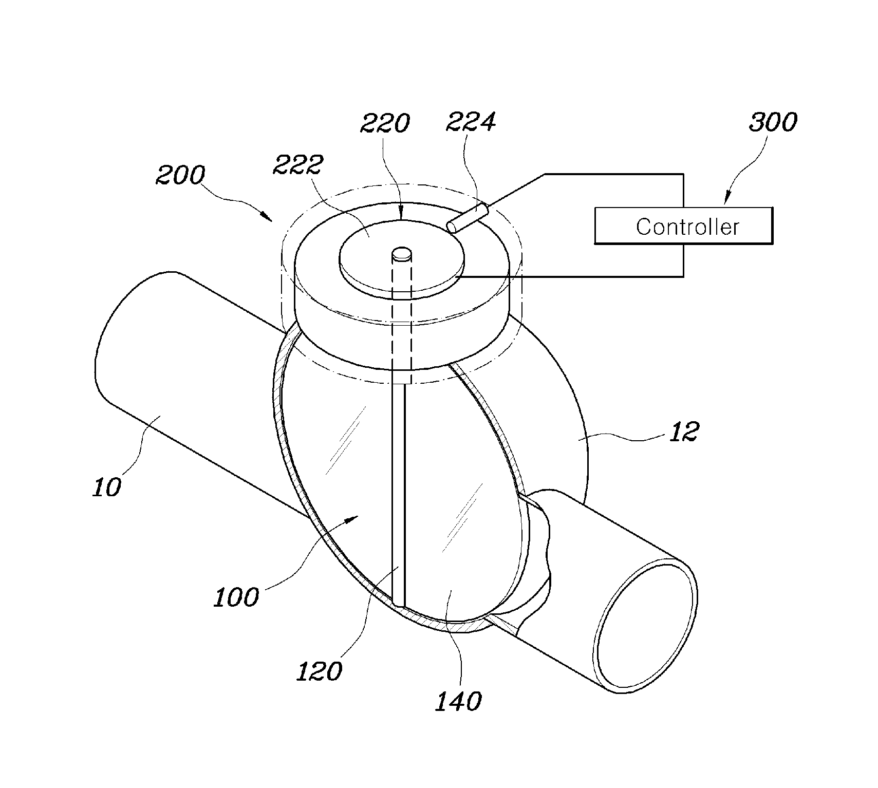
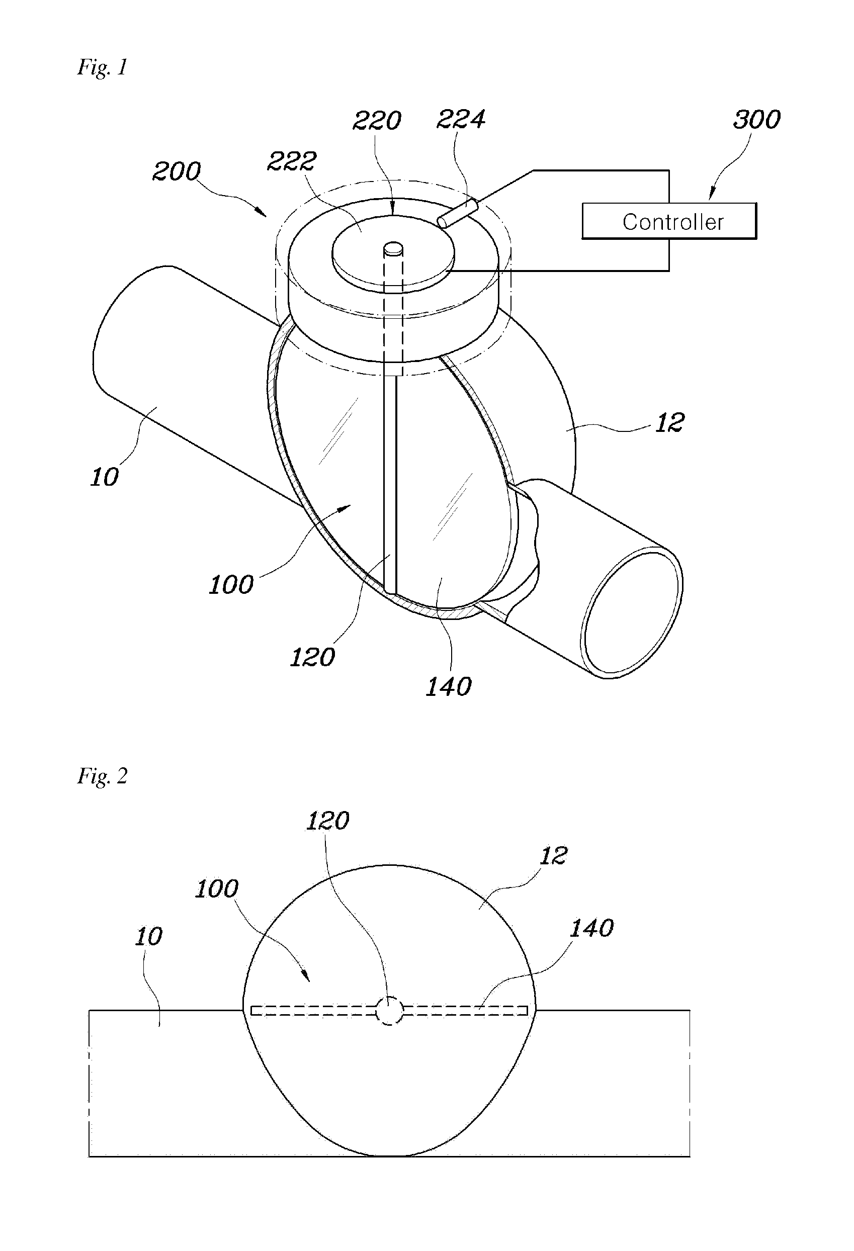
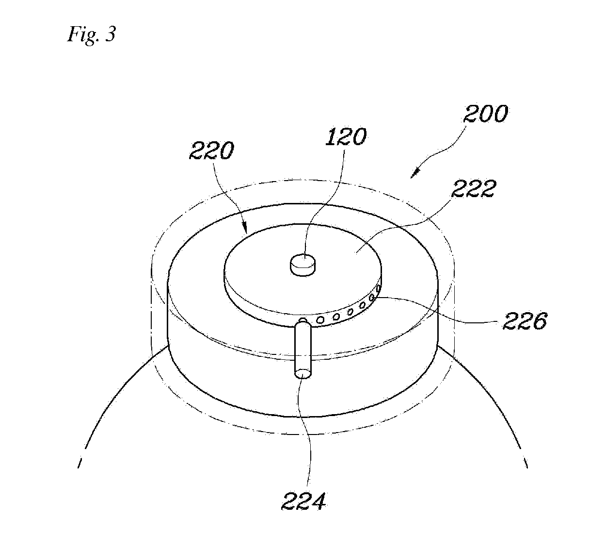
The present invention proposes an apparatus for recovering exhaust kinetic energy to manage energy and improve environmental impact. It uses the kinetic energy of exhaust gas that is ejected under high pressure to generate electricity. The controller can tune discharge noises of the exhaust gas by adjusting the flap, speed of rotation, or rotational torque of the motor generator. This helps to minimize backpressure and improve engine torque and fuel efficiency. The space section formed at the side of the exhaust gas pipe also allows for energy management without adding any exhaust gas pipe to the system, reducing weight and cost. Moreover, the flap can be adjusted to tune the discharge noises to the driver's requirements.

Problems solved by technology

However, conventionally a recycling system which simply recovers and recycles exhaust heat having a high temperature has a problem in that the energy from the exhaust gas that is ejected under a high pressure is discharged and wasted.
However, when the exhaust gas pipe is added, the weight of the vehicle increases, as does material cost and workload, which is problematic.

Method used


Image

  • Apparatus and method for recovering exhaust kinetic energy
  • Apparatus and method for recovering exhaust kinetic energy
  • Apparatus and method for recovering exhaust kinetic energy

Examples


Embodiment Construction

[0023]Reference will now be made in greater detail to an apparatus and method for recovering exhaust kinetic energy according to the present invention, embodiments of which are illustrated in the accompanying drawings. Wherever possible, the same reference numerals will be used throughout the drawings and the description to refer to the same or like parts.

[0024]It is understood that the term “vehicle” or “vehicular” or other similar term as used herein is inclusive of motor vehicles in general such as passenger automobiles including sports utility vehicles (SUV), buses, trucks, various commercial vehicles, watercraft including a variety of boats and ships, aircraft, and the like, and includes hybrid vehicles, electric vehicles, plug-in hybrid electric vehicles, hydrogen-powered vehicles and other alternative fuel vehicles (e.g. fuels derived from resources other than petroleum). As referred to herein, a hybrid vehicle is a vehicle that has two or more sources of power, for example b...


PUM


Abstract

An apparatus and method for recovering exhaust kinetic energy. The apparatus includes a valve assembly, a motor generator and a controller. The valve assembly includes a rotary shaft which is disposed in an exhaust gas pipe and a flap which is disposed on the rotary shaft. The flap is rotated by an exhaust gas that is ejected. The motor generator is connected to the rotary shaft of the valve assembly, and in a first instance generates electricity using a rotational force transmitted from the rotary shaft and in a second instance applies a torque to the rotary shaft. The controller fixes the rotary shaft of the valve assembly at a predetermined angle in the first instance and adjusts the speed of rotation of the rotary shaft by controlling the motor generator in the second instance.

Description

CROSS-REFERENCE TO RELATED APPLICATION[0001]This application claims priority under 35 U.S.C. §119 to Korean Patent Application No. 10-2012-0061563 filed on, Jun. 8, 2012, the disclosure of which is hereby incorporated by reference in its entirety.BACKGROUND[0002]1. Field of the Invention[0003]The present invention relates, in general, to an apparatus for recovering exhaust kinetic energy which recovers kinetic energy from exhaust having a high pressure that is discharged while of a vehicle is being driven.[0004]2. Description of the Related Art[0005]In general, in a vehicle which is equipped with an internal combustion engine, fuel is burned inside the internal combustion engine, and in the process of producing power, high-temperature and high-pressure gas is discharged due to the burning of fuel. This discharge is referred to as exhaust.[0006]Exhaust systems typically directly discharge high-temperature and high-pressure gas that has been burned in the internal combustion engine in...

Claims


Application Information

Patent Timeline
Patent Type & Authority Applications(United States)
IPC IPC(8): F01N5/04H02K57/00
CPCF01N5/04H02K57/003F01N2240/36Y02T10/12H02N11/00Y02T10/64
Inventor WON, JONG SEUNG
Owner HYUNDAI MOTOR CO LTD
Learn More