FPDA Closed Loop Electric Drives Controls

Active Publication Date: 2013-12-12
CATERPILLAR INC
View PDF13 Cites 7 Cited by
  • Summary
  • Abstract
  • Description
  • Claims
  • Application Information

AI Technical Summary

Benefits of technology

This patent describes a controller for a motor that reduces torque ripple and distributes torque production evenly. The controller uses a combination of a field programmable gate array (FPGA) and an application specific integrated circuit (ASIC) to process data in parallel, which speeds up the system and reduces loop times. The controller generates current control parameters based on the motor's speed, position, torque command, and a pre-programmed torque sharing function. The torque sharing function modifies the current in each phase of the motor to produce a more even distribution of torque and minimize torque ripple. The current profiling module uses a lookup map to determine the optimal current target for each phase of the motor. The refinements of the controller reduce the time required for motor control and make it more efficient.

Problems solved by technology

Such closed loop processes are executed at predefined rates that are essentially limited by the capabilities of the microprocessor and the manner by which the algorithm is implemented by the microprocessor.

Method used


Image

  • FPDA Closed Loop Electric Drives Controls
  • FPDA Closed Loop Electric Drives Controls
  • FPDA Closed Loop Electric Drives Controls

Examples


Embodiment Construction

[0050]Reference will now be made in detail to specific embodiments or features, examples of which are illustrated in the accompanying drawings. Generally, corresponding reference numbers will be used throughout the drawings to refer to the same or corresponding parts.

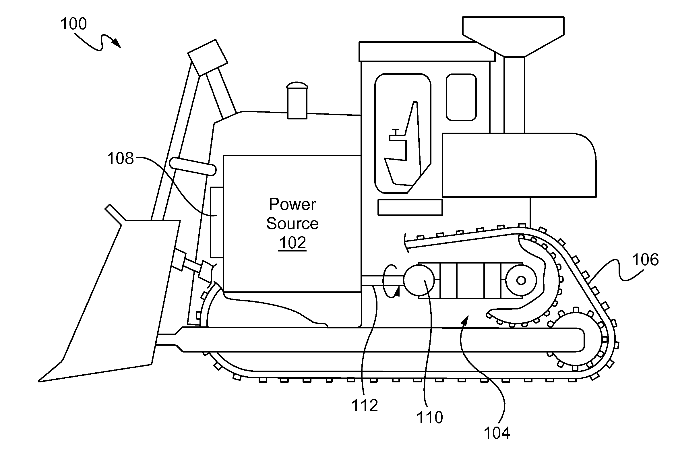
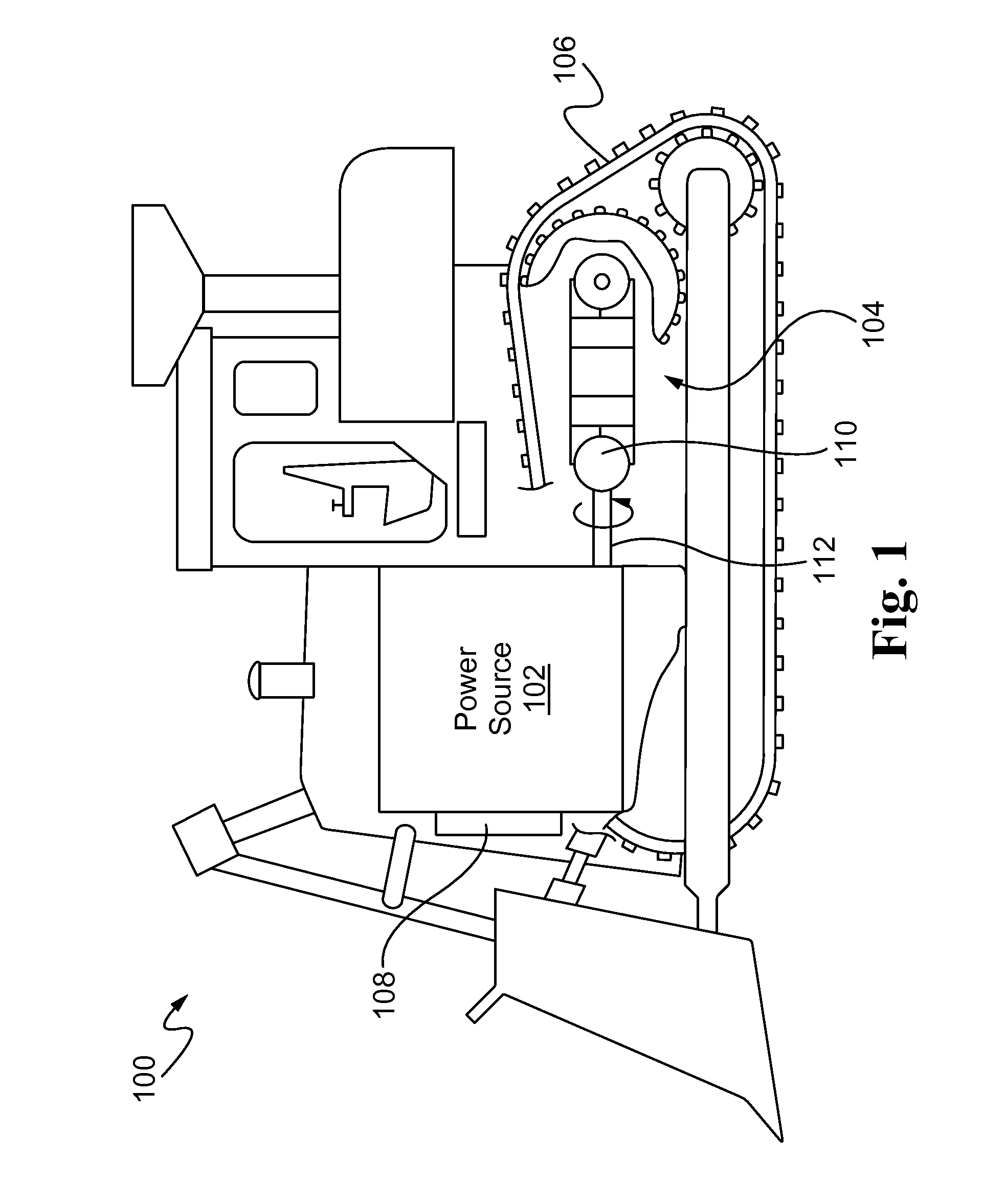
[0051]FIG. 1 diagrammatically illustrates one exemplary embodiment of a machine 100 that may employ electric drive means to generate electrical energy from mechanical energy or vice versa. In the particular embodiment of FIG. 1, for instance, the machine 100 may include a power source 102 coupled to an electric drive 104 for causing movement via a traction device 106. Moreover, the power source 102 may be configured to mechanically transmit power to an electric machine 110, such as a motor / generator, or the like, of the electric drive 104 via a coupling or axially rotating drive shaft 112. Such mobile machines 100 may be used as a work machine for performing a particular type of operation associated with an industry, su...


PUM


Abstract

A control system for a switched reluctance (SR) machine is provided. The control system may include a converter circuit that is operatively coupled to the SR machine, and a controller in communication with the converter circuit. The controller may be configured to execute two or more processes in parallel, wherein the processes include generating a torque command based on one or more of bus voltage, machine current, rotor speed and rotor position, determining a first set of current control parameters based on the torque command and the rotor speed, determining a second set of current control parameters based on one or more of the torque command, the rotor speed and the rotor position, selecting one of the first and second sets of current control parameters based on the rotor speed, and operating the gates according to the selected set of current control parameters.

Description

TECHNICAL FIELD[0001]The present disclosure relates generally to switched reluctance machines, and more particularly, to systems and methods of controlling electric drives of switched reluctance machines.BACKGROUND[0002]With the growing interest in energy conservation, increasingly more machines, such as mobile industrial work machines or stationary power generation machines, are supplied with electric drive assemblies or systems for operating various tools or functions of the machine. Ongoing developments in electric drives have made it possible for electrically driven machines to effectively match or surpass the performance of mechanically driven machines while requiring significantly less fuel and overall energy. As electric drives become increasingly more commonplace with respect to such machines, the demand for more efficient generators and techniques for controlling same has also increased.[0003]Among the various types of electrically driven machines available for use with suc...

Claims


Application Information

Patent Timeline
IPC IPC(8): H02P6/08
CPCH02P25/087B60L2200/40Y02T10/642Y02T90/16B60L2220/18H02P25/0805Y02T10/64
Inventor GERDES, JESSESIEGLE, JAMESHARTMAN, MARKTHOMAS, AARON LUTHERWAI, JACKSON
Owner CATERPILLAR INC
Why Eureka
Try Eureka