Optimized Cross-Ply Orientation in Composite Laminates

a cross-ply orientation and laminate technology, applied in the field of composite laminates, can solve the problems of not fully optimizing to match performance requirements, skin that is heavier than desired for a particular application, etc., and achieve the effects of reducing weight, improving structural strength, stiffness and resistance to splitting and crack propagation, and reducing the weight of the structur

Active Publication Date: 2013-12-12
THE BOEING CO
View PDF5 Cites 21 Cited by
  • Summary
  • Abstract
  • Description
  • Claims
  • Application Information

AI Technical Summary

Benefits of technology

This patent describes a way to make composite structures, like aircraft skins, that are stronger and lighter. It does this by using fewer layers of material in the composite laminate and optimizing the orientation of the cross-plies (fiber orientations) to improve the structure's strength and stiffness. The reduction in the number of layers can save money on materials and labor costs. The optimized orientation of the cross-plies can be used in existing aircraft designs without needing to change the wing design. The patent also mentions that a three to five percent reduction in the weight of an aircraft wing box can be achieved using the optimized arrangement of the cross-plies. Overall, this patent provides a way to make stronger and lighter composite structures while reducing weight and costs.

Problems solved by technology

Although the number of plies in the laminate may vary at different locations along the wing, the angular orientation of the plies may be substantially constant over the length of the wing, and therefore not fully optimized to match performance requirements at individual locations on the wing.
The use of these differing ply orientations allow the composite laminate structure to better resist bending, shear, torsional and bearing loads for a given application, but the use of constant orientations of the plies may result in a skin that is heavier than desired for a particular application.

Method used


Image

  • Optimized Cross-Ply Orientation in Composite Laminates
  • Optimized Cross-Ply Orientation in Composite Laminates
  • Optimized Cross-Ply Orientation in Composite Laminates

Examples


Embodiment Construction

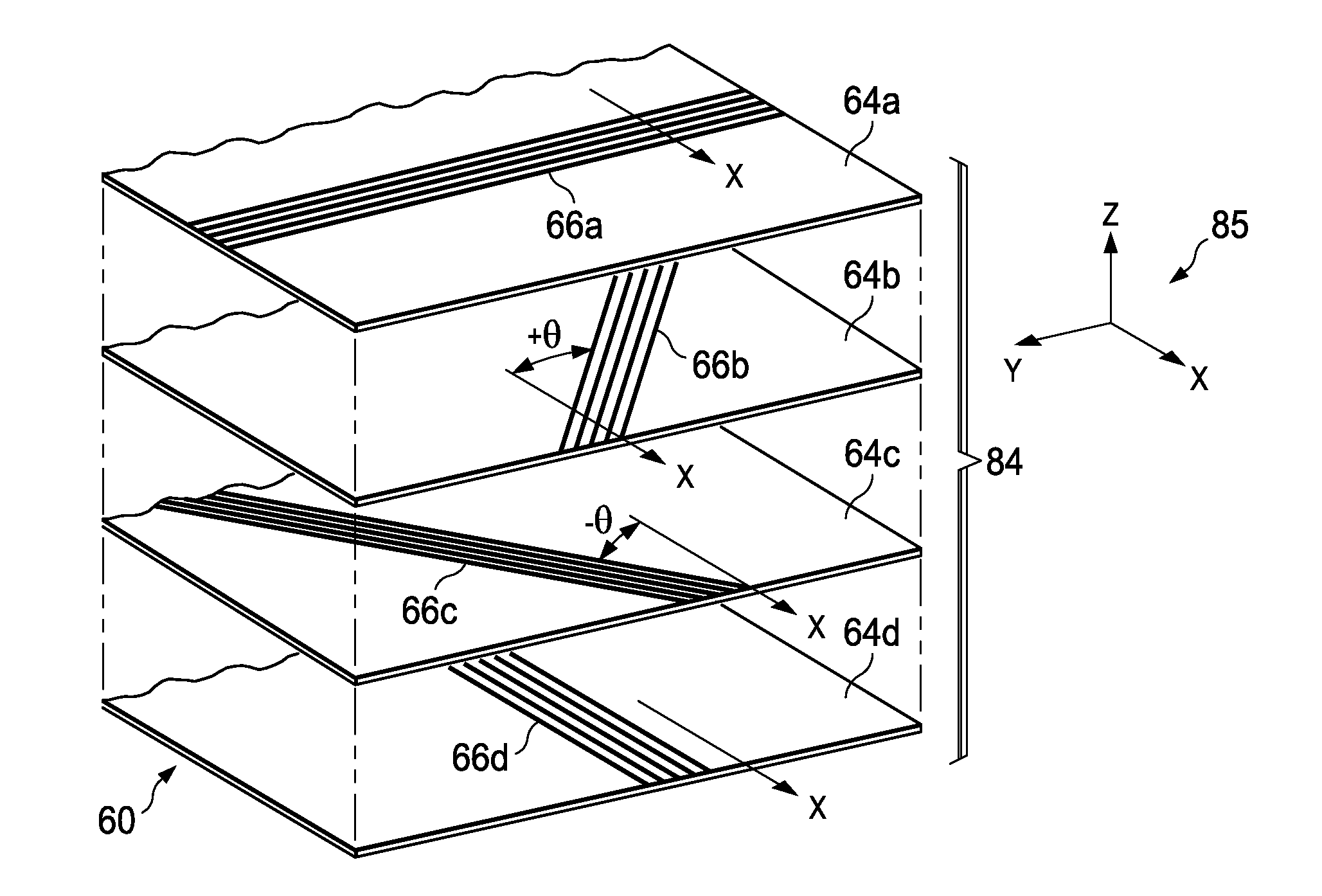
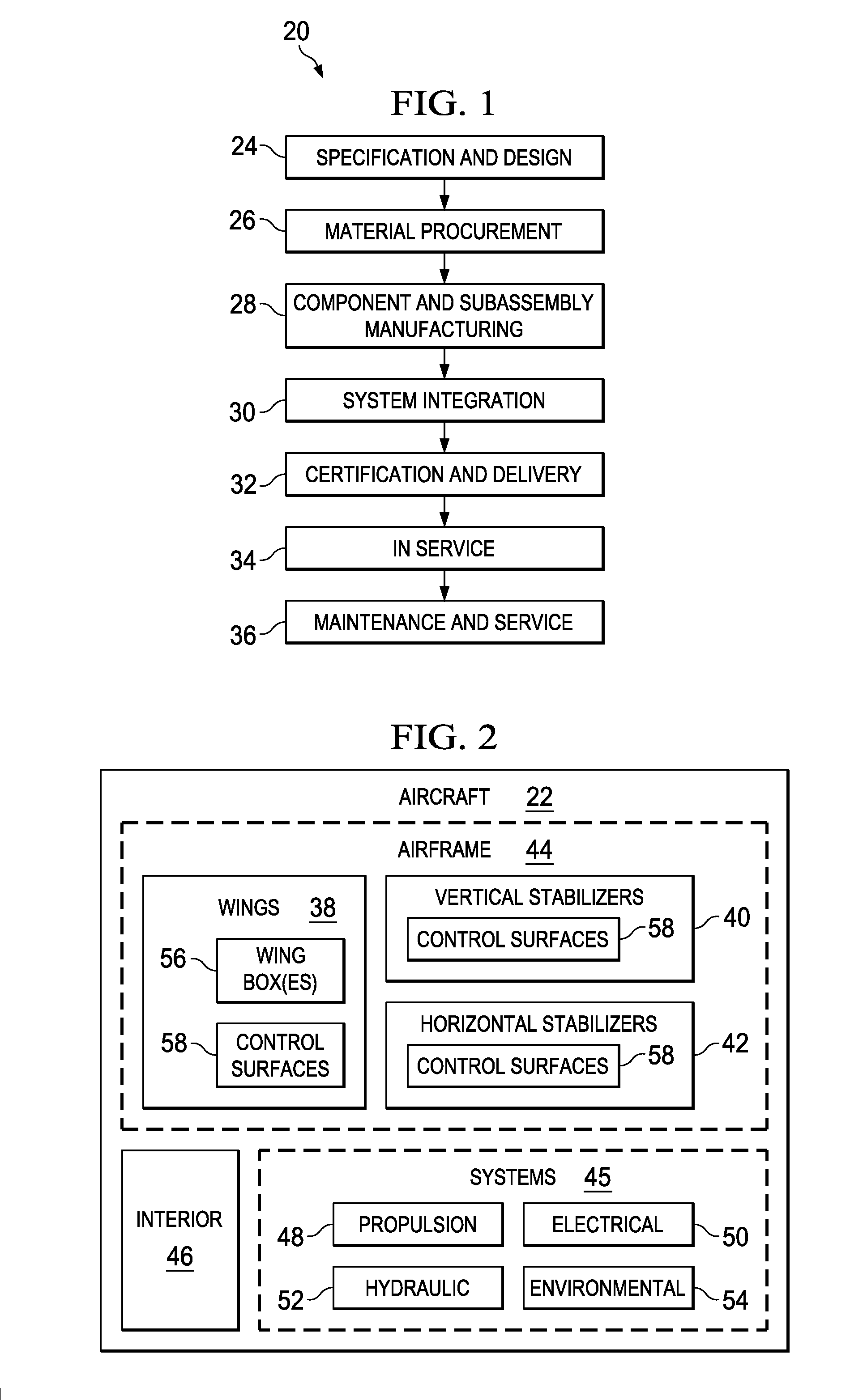
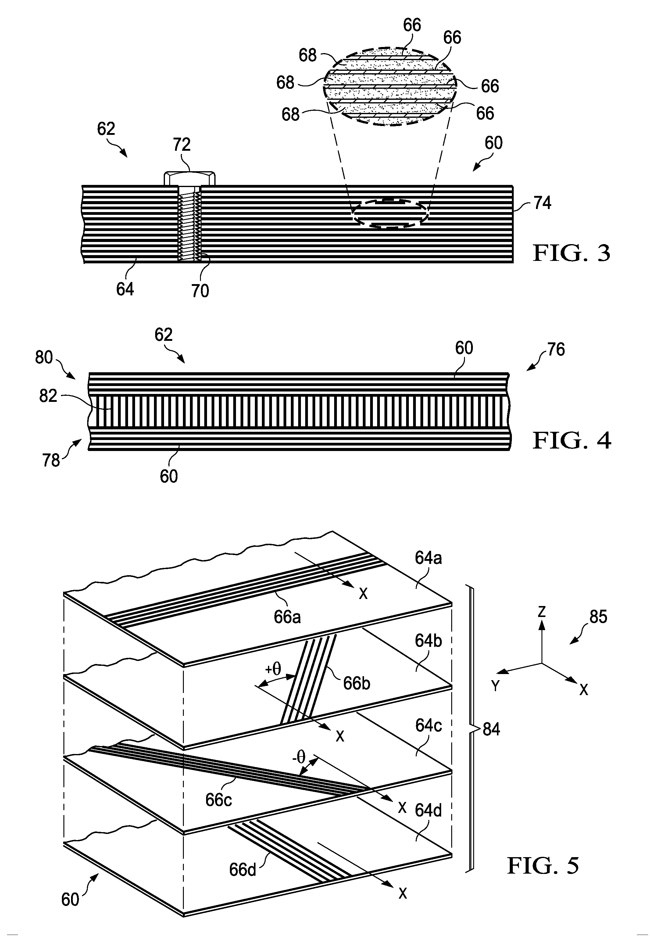
[0026]The disclosed embodiments relate to a composite laminate and related fabrication method that may be employed to fabricate any of a variety of composite laminate structures. The embodiments may find use in numerous fields, particularly in the transportation industry, including for example, aerospace, marine, automotive applications and other applications where light weight composite laminates are employed. Thus, referring now to FIGS. 1 and 2, embodiments of the disclosure may be used in the context of an aircraft manufacturing and service method 20 as shown in FIG. 1, and an aircraft 22 as shown in FIG. 2. Aircraft applications of the disclosed embodiments may include, for example, without limitation, skins (not shown in FIG. 2 but discussed later) forming part of wings 38, a vertical stabilizer 40 and horizontal stabilizers 42, all of which form part of an airframe 44. During pre-production, exemplary method 20 may include specification and design 24 of the aircraft 22 and ma...


PUM

PropertyMeasurementUnit
Angleaaaaaaaaaa
Angleaaaaaaaaaa
Angleaaaaaaaaaa

Abstract

A composite laminate has a primary axis of loading and comprises a plurality resin plies each reinforced with unidirectional fibers. The laminate includes cross-plies with fiber orientations optimized to resist bending and torsional loads along the primary axis of loading.

Description

BACKGROUND INFORMATION[0001]1. Field:[0002]The present disclosure generally relates to composite laminates, such as those used in aircraft, and deals more particularly with a fiber reinforced resin laminate having cross-plies with optimized fiber orientations.[0003]2. Background:[0004]Fiber reinforced resin laminates, such as carbon fiber reinforced plastics (CFRP), are widely used in aerospace and other applications because of their favorable strength-to-weight ratio. These composite laminates may be fabricated by laying up multiple plies of unidirectional reinforcing fibers held in a resin matrix, commonly known as prepreg. The plies in the layup may have differing fiber orientations arranged in an order that results in the required laminate strength and stiffness for a particular application. For example, in aircraft skins, the composite laminate may comprise groups of plies respectively having reinforcing fibers oriented at 0, +45, −45 and 90 degrees relative to a reference axis...

Claims


Application Information

Patent Timeline
IPC IPC(8): B32B5/12B32B37/00
CPCB29L2031/3076B32B5/12B29C70/30B29L2031/3085B32B5/26B32B2307/544B32B2307/546B32B2605/18Y10T156/10Y10T428/24124B29C70/202Y02T50/40B32B5/28B32B5/04B32B27/02B64C3/26B64C3/20B29K2105/0881
Inventor KISMARTON, MAX U.
Owner THE BOEING CO
Why Eureka
Try Eureka