Process for separation and recovery of cuttings, emulsion and slurry components

Inactive Publication Date: 2013-12-12
C&E RECLAMATION
View PDF14 Cites 17 Cited by
  • Summary
  • Abstract
  • Description
  • Claims
  • Application Information

AI Technical Summary

Benefits of technology

[0012]Yet further embodiments of the disclosure can be characterized as a system including a thermal desorber and a hot filter. The thermal desorber can receive an oilfield waste feed and apply thermal energy to the oilfield waste feed in order to vaporize liquid components in the oilfield waste feed. This can generate a first vapor stream and a solids stream. The solids stream can include a fir

Problems solved by technology

However, these fluids not only lubricate the drill bit, but also move drill cuttings (e.g., mineral fines, salt brine, and crude oil) to the surface, thus turning the drilling fluids into oilfield wastes (or “waste”) that eventually require treatment and/or disposal.
At this point, the oilfield wastes require disposal, yet merely dumping such concoctions into the ground is not a feasible option.
Yet, these methods have been so environmentally hazardous that North Dakota outlawed the practice in 2012 and similar prohibitions will likely follow, thus creating the need for alternative treatment and/or disposal solutions.
Currently North Dakota has three secure hazardous waste landfills where oilfield wastes can be disposed of, but this requires expensive transport of the wastes and is unsustainable.
However, on-site treatment is ineffective to remove all solid fines (e.g., <10 μm) in the recycled drilling fluids, and thus the recycled drilling fluids eventually become unusable because of an accumulation of solid fines (e.g., 20%-30%).
Thus, these on-site treatments merely reduce the rate of waste disposal rather than eliminate an amount of waste that eventually is put into landfills.
Because on-site pit disposal is becoming less of an o

Method used


Image

  • Process for separation and recovery of cuttings, emulsion and slurry components
  • Process for separation and recovery of cuttings, emulsion and slurry components
  • Process for separation and recovery of cuttings, emulsion and slurry components

Examples


Embodiment Construction

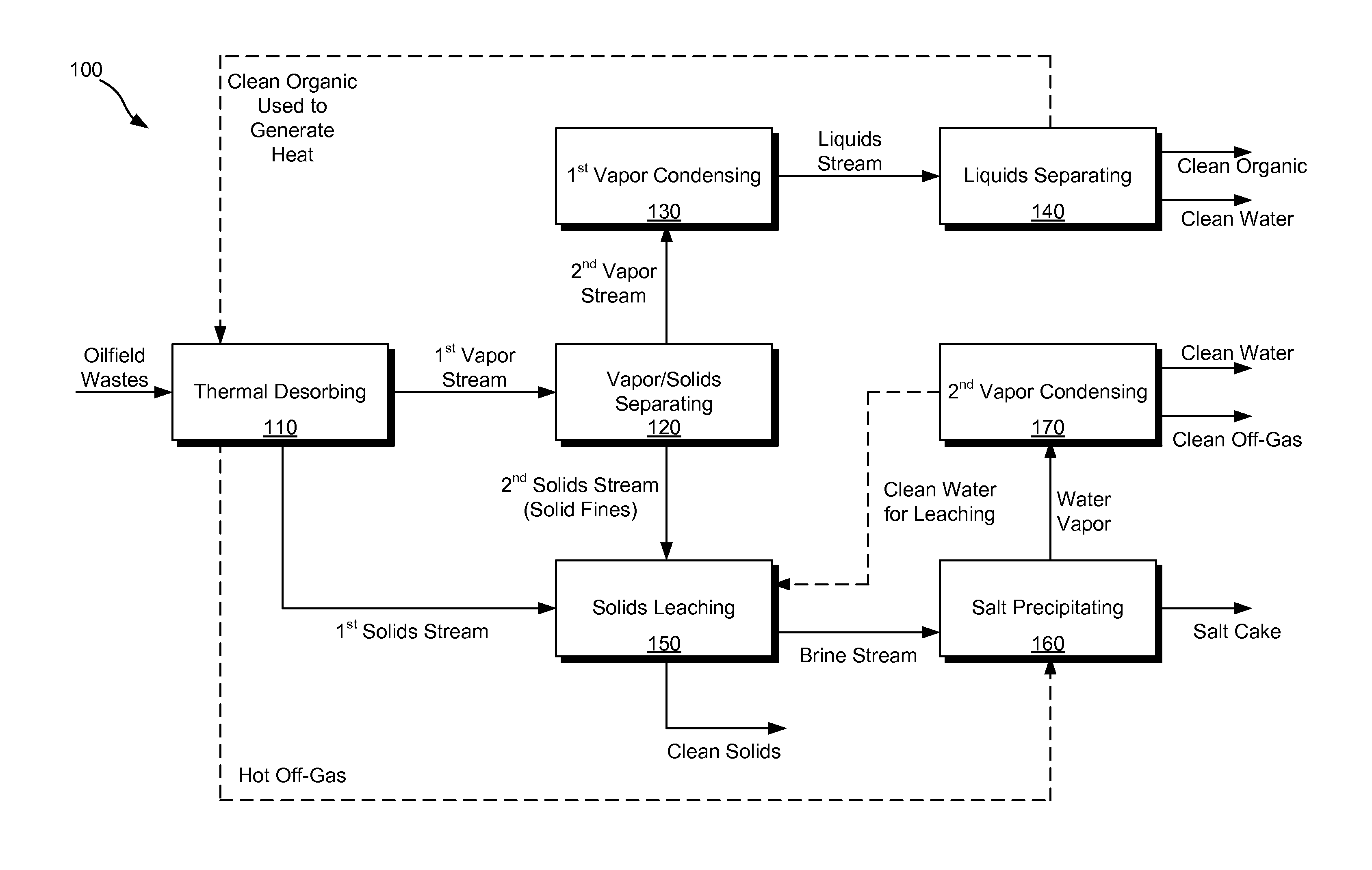
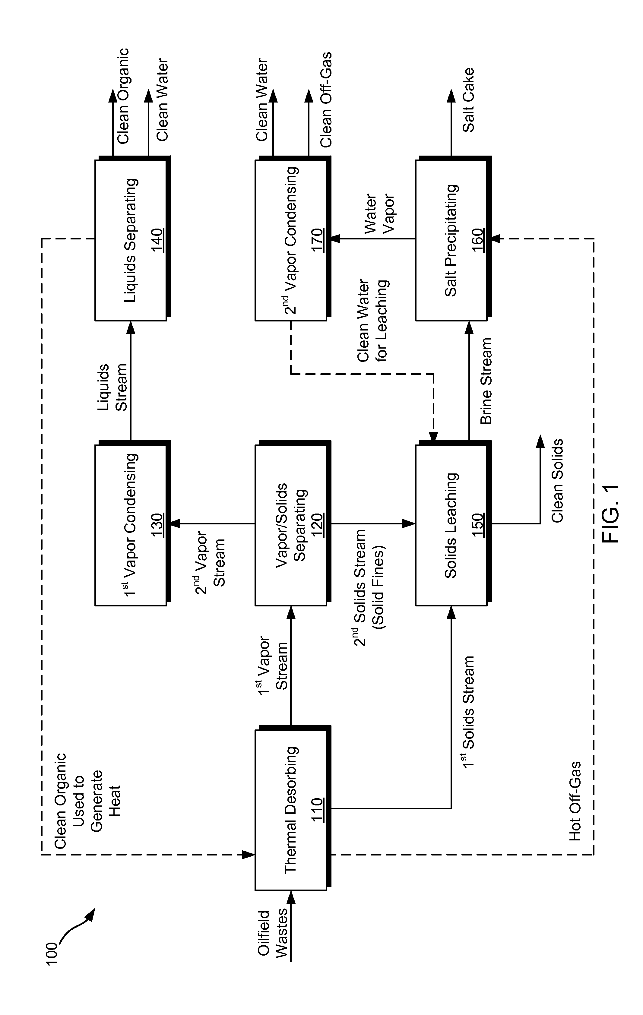
[0016]To realize the aforementioned benefits and to overcome the disadvantages of existing technologies, Applicant has developed on-site systems, methods, and apparatus for separating and recovering major components of oilfield wastes. Such solutions are particularly applicable to oil / water emulsions having solid fines in them, since such waste emulsions are typically intractable for traditional treatment systems. The systems, methods, and apparatus of this disclosure are even applicable to waste feeds comprising an emulsion of organics (e.g., hydrocarbons) and water having a greater viscosity than the two phases in isolation, and solid fines having a specific gravity approaching that of the organics and water, this waste feed is intractable for traditional treatment methods.

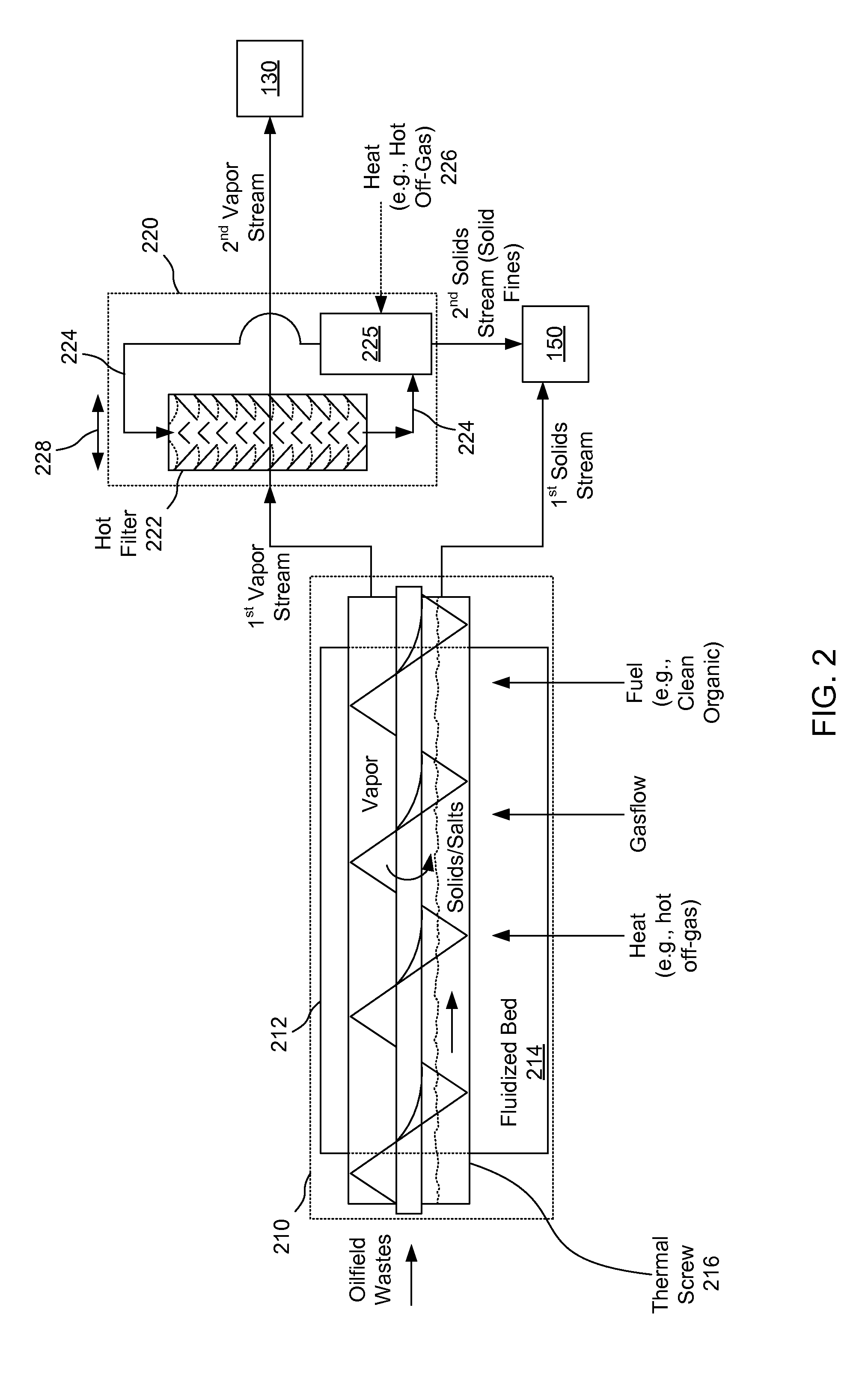
[0017]The inventor first applied thermal desorption to the oilfield wastes, which was a novel approach in and of itself, only to find that the supposed ‘treated’ vapors were filled with solid fines, and once the...


PUM


Abstract

This disclosure describes systems, methods, and apparatus for separating and purifying components from mixtures and emulsions containing hydrocarbons, water, salt, and mineral solids. Key unit operations are thermal desorbing, hot filtering, direct contact condensing, solids leaching, evaporating, and salt precipitating. Preferred embodiments of the process and system use process-generated fuel, leach water, and hot combustion gas to conduct thermal desorption, solids leaching, and salt precipitating. Use of process generated streams for key unit operations greatly reduces the need for purchased utilities and contributes both to process efficiency and economy.

Description

CLAIM OF PRIORITY UNDER 35 U.S.C. §119[0001]The present application for patent claims priority to Provisional Application No. 61 / 652,615 entitled “PROCESS FOR SEPARATION AND RECOVERY OF CUTTINGS, EMULSION AND SLURRY COMPONENTS” filed May 29, 2012, and assigned to the assignee hereof and hereby expressly incorporated by reference herein.FIELD OF THE INVENTION[0002]The present disclosure relates generally to fossil fuel production treatment, and in particular to treating wastes from fossil energy exploration, production, transportation, and refining.BACKGROUND OF THE INVENTION[0003]As compared to traditional vertical hydrocarbon drilling equipment, horizontal drilling now requires a new level of drill bit lubrication. These new drilling fluids, sometimes referred to as “invert mud,” typically comprise mixtures of aqueous and organic liquid phases that are emulsified and bound together by various surface active agents (surfactants). The aqueous liquid phase is often salt brine while th...

Claims


Application Information

Patent Timeline
IPC IPC(8): C10G70/00B01D3/00
CPCC10G70/00B01D3/009C10G1/02F26B3/0923F26B3/20F26B17/20F26B2200/18
Inventor DRAKE, RONALD N.
Owner C&E RECLAMATION
Why Eureka
Try Eureka