
Apparatus for guiding tube processing devices

a technology for processing devices and guiding tubes, which is applied in the direction of tube shearing machines, soldering apparatuses, auxillary welding devices, etc., can solve the problems of one diameter dimension, non-tight weld seams, and troublesome oxide films, and achieves high degree of flexibility, high degree of tensile strength, and easy elastic deformation or bent

Active Publication Date: 2013-12-19
GEORG FISCHER WAVIN AG
View PDF7 Cites 3 Cited by
  • Summary
  • Abstract
  • Description
  • Claims
  • Application Information

AI Technical Summary

Benefits of technology

The invention is a frame apparatus for processing tubes that has two parallel bands with a flat rectangular cross section. The bands can be made of spring steel or other metal materials, or plastic or fiber-reinforced plastic. The bands have a characteristic of adapting to the circumference of the tube in a precise fitting manner, being easily positioned along its length. They are stiff against torsion, meaning they can be distorted along their length only to a small degree, but can easily be bent or elastically deformed. The frame is formed by connecting the bands to a carrier, which can be easily disassembled for transport and re-assembly. The bands can also be directly fastened onto the carrier. The invention is advantageous when the spacers are smaller in length than the bands, making it easy to guide the tube processing device in an optimal manner.

Problems solved by technology

An oxide film is just as troublesome when welding tubes, as welding without removing the oxide film by scraping it off can result in a non-tight weld seam.
A disadvantage of said planing device is that it can only be used for one diameter dimension.
Said planing device is only suitable for plastic tubes which have a smaller diameter which can still be handled.
It is not suitable for large-dimensioned plastic tubes which are used, for example, as gas lines.
A disadvantage of said planing device is that it is only suitable for processing at the edge of a tube and not in the middle of an installed pipeline as the device requires a stop which abuts against the end face of the tube and, as a result, determines the spacing and takes over the guiding of the plane.
A disadvantage of the above-mentioned disclosures is also that the apparatuses can only be used in each case for one application, namely for the planing of the tubes.

Method used


Image

  • Apparatus for guiding tube processing devices
  • Apparatus for guiding tube processing devices
  • Apparatus for guiding tube processing devices

Examples


Embodiment Construction

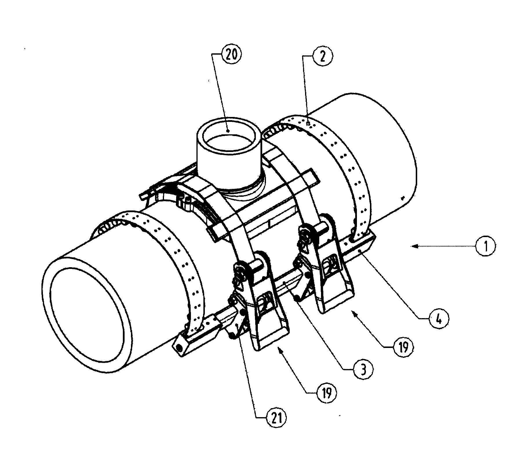
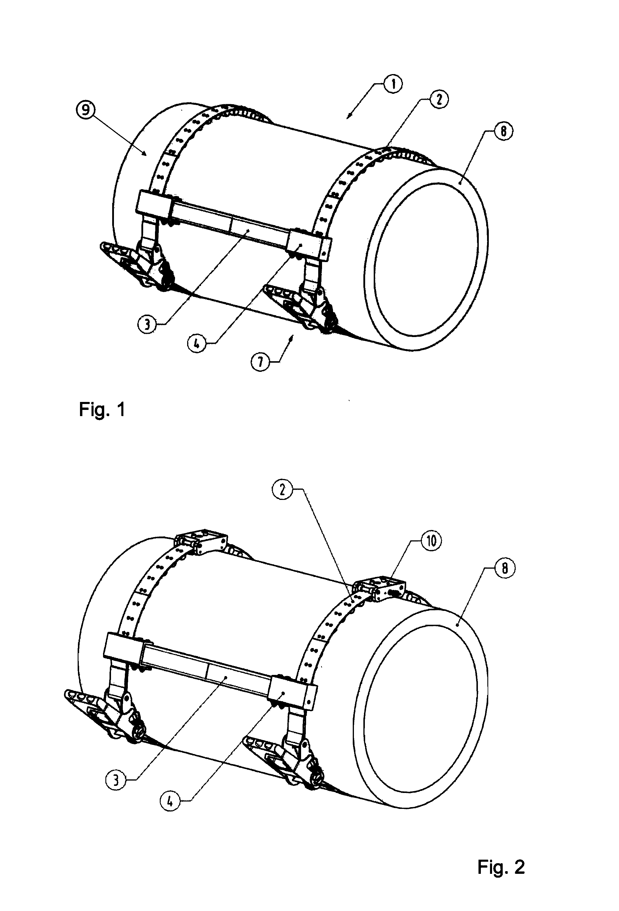
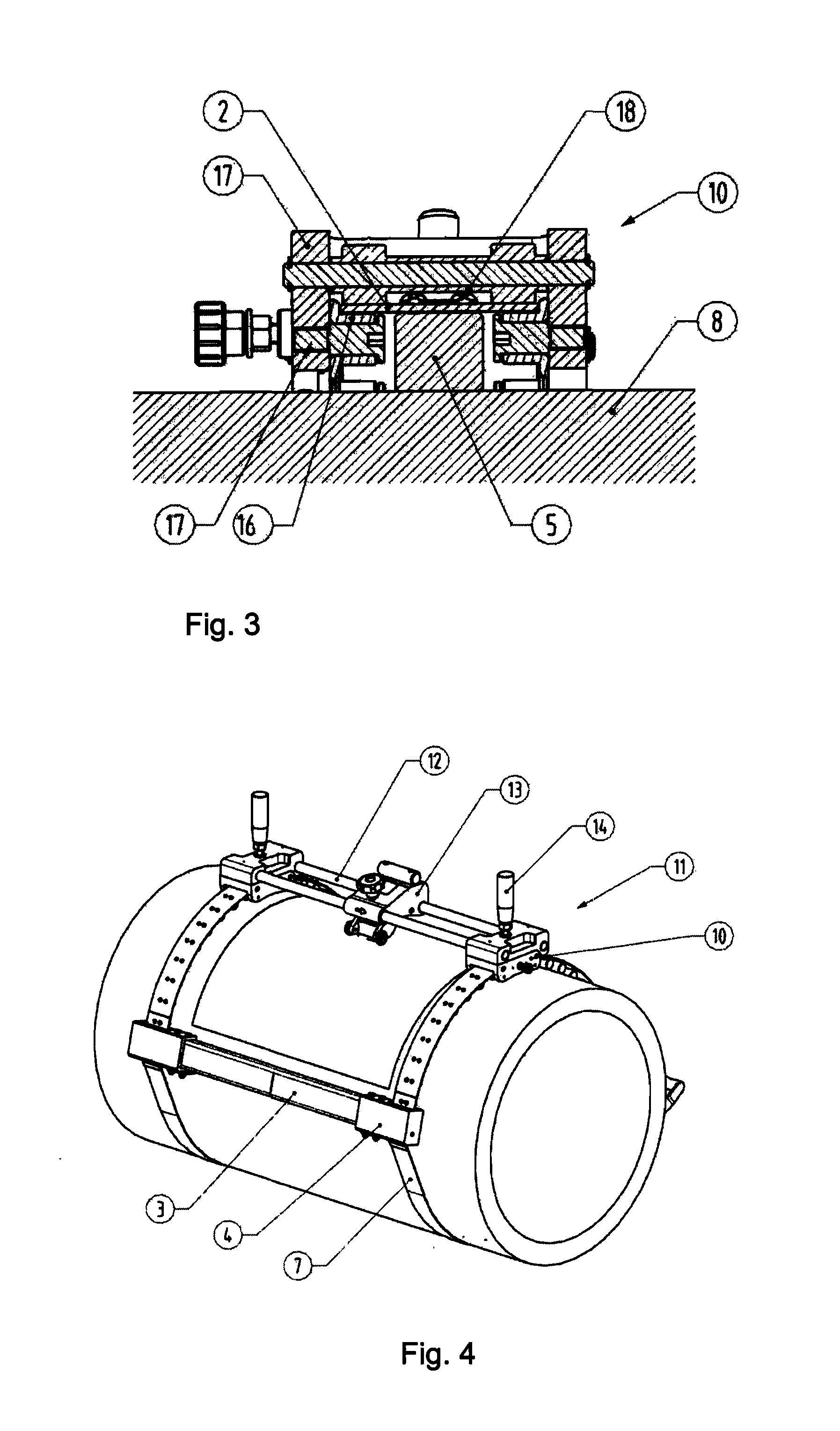
[0026]FIG. 1 shows the apparatus according to the invention mounted on the circumference. The two bands 2, which are preferably of spring steel, adapt to the course of the circumference of the tube 8. The material of the bands 2 is selected such that it has a high degree of torsional strength as well as being stiff to torsion, that means that the bands 2 can hardly be deformed along their length, however, they adapt easily to the circumference of the tube 8 by means of their high degree of flexibility along their length. By means of the spacers 5 which are arranged on the band underside 6, the band is at a constant spacing from the outer circumference of the tube 8 or from the surface thereof. The two bands 2 of the apparatus extend parallel with respect to one another. The band ends of the two bands 2, which are located on the same side of the circumference or which are located side by side, are in each case connected together by means of a carrier 3. The apparatus 1 forms, as a re...


PUM

PropertyMeasurementUnit
Metallic bondaaaaaaaaaa
Circumferenceaaaaaaaaaa

Abstract

An apparatus for guiding tube processing devices, in particular planing devices, wherein the apparatus is arranged on an outer circumference of the tube to be processed, wherein the apparatus has at least two bands which extend in parallel.

Description

BACKGROUND OF THE INVENTION[0001]The invention relates to an apparatus for guiding tube processing devices, in particular planing devices, wherein the apparatus is to be arranged on the outer circumference of the tube to be processed.[0002]Remachining work which serves for connecting further lines or branches, is often carried out on plastic tubes or plastic pipework.[0003]For example, to fit branch sockets or welding saddles which are welded to the main line, it is necessary to plane off the outer surface of the tube at the weld point in order to remove dirt inclusions from the production process or even material changes brought about by ageing which, for example, can occur on the surface of the tube as a result of UV damage or weather.[0004]In addition, an oxide film is formed when plastic tubes are stored. An oxide film is just as troublesome when welding tubes, as welding without removing the oxide film by scraping it off can result in a non-tight weld seam.[0005]Processing the ...

Claims


Application Information

Patent Timeline
IPC IPC(8): B23Q9/02
CPCB23Q9/02B23D9/00B23D79/06B23D79/10B23K37/0536B23K31/027B23K2101/06B23D21/04
Inventor HOGG, CHRISTIANMAYER, KARL-HEINZTINIUS, MICHAEL
Owner GEORG FISCHER WAVIN AG
Learn More