
Method for Synthesizing Fluorine Compound by Electrolysis and Electrode Therefor

Inactive Publication Date: 2013-12-26
CENT GLASS CO LTD
View PDF5 Cites 0 Cited by
  • Summary
  • Abstract
  • Description
  • Claims
  • Application Information

AI Technical Summary

Benefits of technology

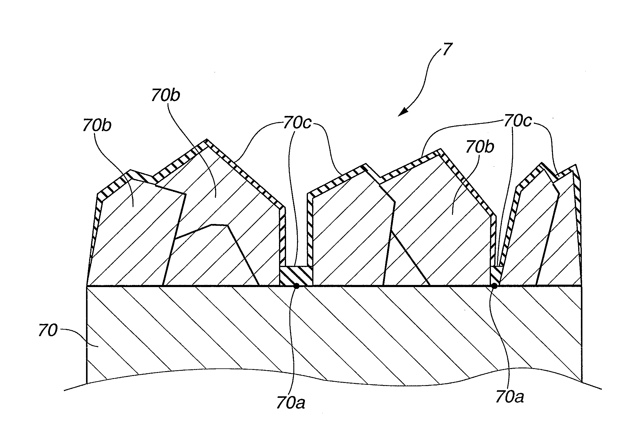
The present invention provides an electrode for electrolytic synthesis of fluorine compounds that can prevent a decrease in effective electrolysis area and allow stable electrolysis by forming a metal fluoride-containing coating layer on the surface of the electrode substrate. This coating layer has high durability and electrical conductivity, which ensures stable operation of the electrode in the electrolytic bath of hydrogen fluoride-containing molten salt.

Problems solved by technology

When the graphite fluoride layer grows to a large thickness on the surface of the carbon material, the area of contact of the electrode with an electrolytic solution in the electrolytic bath becomes reduced to cause a problem of decrease in current flow (which is so called “anode effect”).
In the conventional coating technique, however, it has been practically difficult to completely cover the carbon substrate surface by the conducting diamond coating layer with no minute defects because the conducting diamond coating applied to the carbon substrate is in polycrystalline form.

Method used


Image

  • Method for Synthesizing Fluorine Compound by Electrolysis and Electrode Therefor
  • Method for Synthesizing Fluorine Compound by Electrolysis and Electrode Therefor

Examples


example 1

[0056]Using a hot filament CVD apparatus, an electrolytic electrode (anode 7) coated with boron-doped conducting diamond (also simply referred to as “boron-doped diamond”) was produced by the following procedure. Herein, an amorphous carbon substrate was used as an electrode substrate 70.

[0057]The entire front and back surfaces of the electrode substrate 70 were polished with the use of diamond-containing abrasives. The polished electrode substrate 70 was immersed in an ultrasonic cleaner filled with an ethanol aqueous solution in which diamond particles of 5 nm average size were dispersed, thereby performing diamond nucleation enhancement treatment on the entire surfaces of the electrode substrate 70.

[0058]After that, the electrode substrate 70 was dried and placed under a filament inside the hot filament CVD apparatus. Film forming operation was then conducted for 8 hours under the conditions that: the temperature of the filament was maintained at 2200° C.; the pressure inside the...

example 2

[0063]An electrolytic electrode (anode 7) coated with boron-doped diamond was produced in the same manner as in Example 1, except that the concentration of nickel ions in the molten salt of KF-2HF system was adjusted to 30 ppm. Using the thus-obtained electrode, electrolysis reaction was performed by the same procedure under the same electrolysis conditions as in Example 1. The electrolytic voltage was 8 V±0.1 V before and after a lapse of 24 hours.

[0064]It has been shown by the above results that it was also possible to perform the electrolysis reaction stably, with a small change in electrolytic voltage before and after the electrolysis reaction, while limiting the growth of a graphite fluoride layer even in the case where the nickel ion concentration was adjusted to 30 ppm. When a portion of the electrode substrate after the electrolysis reaction was taken as a sample and observed by SEM in the same manner as above, there was seen no separation of the conducting diamond layer and...


PUM

PropertyMeasurementUnit
Fractionaaaaaaaaaa
Fractionaaaaaaaaaa
Electrical conductoraaaaaaaaaa

Abstract

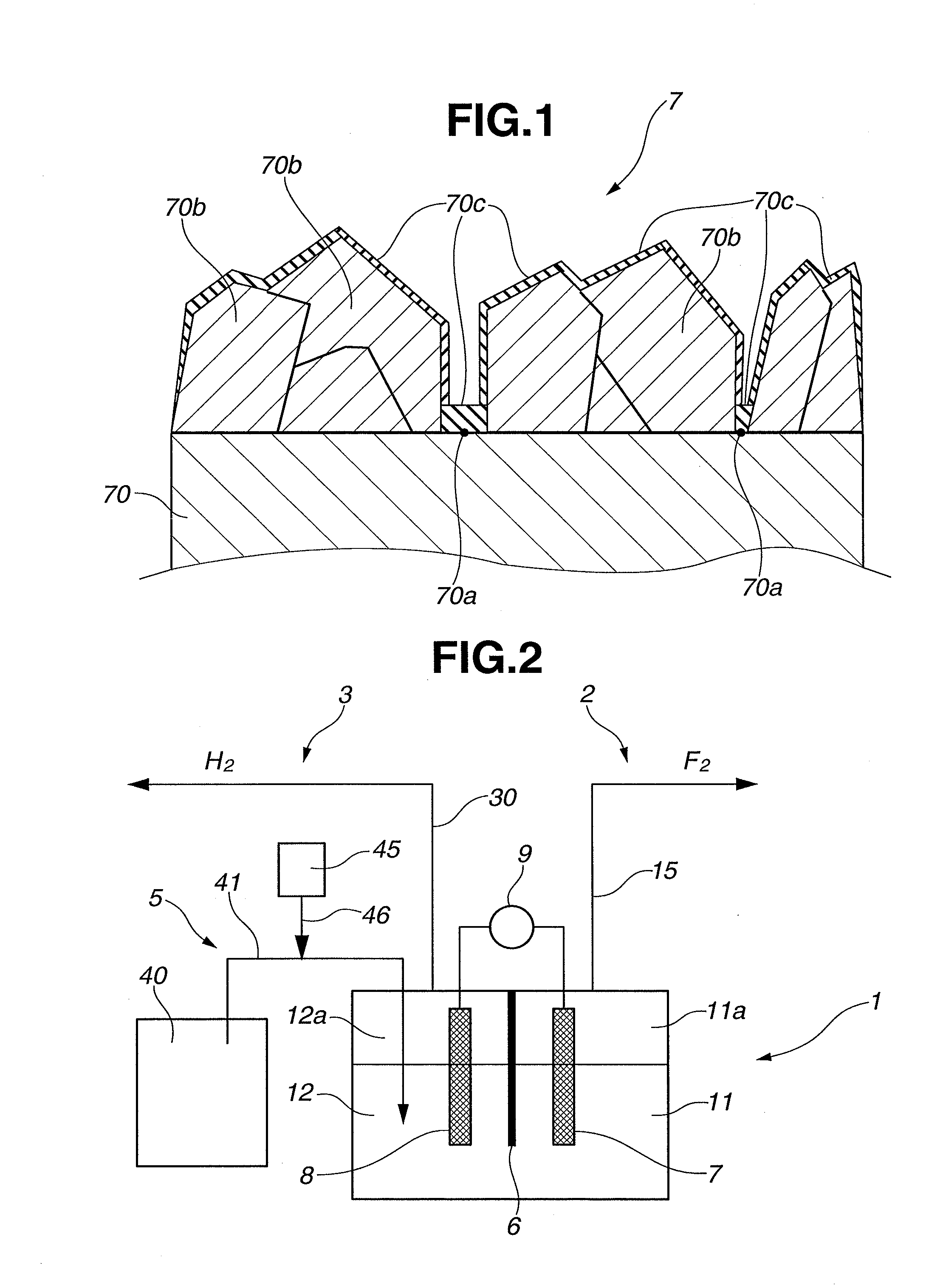
Disclosed is an electrode for electrolytic synthesis of a fluorine compound, including: an electrode substrate having at least a surface thereof formed of a conductive carbon material; a conducting diamond layer formed on a part of the surface of the electrode substrate; and a metal fluoride-containing coating layer formed on an exposed part of the electrode substrate that is uncovered by the conducting diamond layer. It is possible for the electrolytic synthesis electrode to limit the growth of a graphite fluoride layer on the electrode surface, prevent decrease in effective electrolysis area and allow stable electrolysis in an electrolytic bath of a hydrogen fluoride-containing molten salt.

Description

TECHNICAL FIELD[0001]The present invention relates to an electrode and method for electrolytic synthesis of a fluorine compound by the use of an electrolytic bath of a hydrogen fluoride-containing molten salt.BACKGROUND ART[0002]In conventional electrolytic synthesis methods in which fluorine compounds e.g. fluorine, nitrogen trifluoride etc. are produced by electrolysis of hydrogen fluoride in electrolytic baths of hydrogen fluoride-containing molten salts, electrodes of carbon materials are mainly used as anodes. It is however known that, in the case of using such a carbon material electrode in the electrolytic synthesis of the fluorine compound, an insulating layer of graphite fluoride e.g. (CF)n grows on a surface of the carbon material. When the graphite fluoride layer grows to a large thickness on the surface of the carbon material, the area of contact of the electrode with an electrolytic solution in the electrolytic bath becomes reduced to cause a problem of decrease in curr...

Claims


Application Information

Patent Timeline
IPC IPC(8): C25B11/04C25B1/24
CPCC25B11/0478C25B1/245C25D3/66C25D9/06C25B11/043C25B11/091
Inventor MORI, ISAMUYAO, AKIFUMIKIKUCHI, AKIOUYONEKURA, MASAAKIHORIUCHI, HIROSHI
Owner CENT GLASS CO LTD
Learn More