Induction heating apparatus for pipeline connections

a technology of induction heating and pipeline connection, which is applied in the field of induction heating apparatus, can solve the problems of affecting the heating effect of the mainline, the deformation of the mainline coating, and the difficulty of heating a 36′′ or a 48′′ pipe with flame, etc., and achieves the effect of convenient flexing, convenient continuous current flow, and low cos

Inactive Publication Date: 2013-12-26
SHAWCOR LTD
View PDF3 Cites 23 Cited by
  • Summary
  • Abstract
  • Description
  • Claims
  • Application Information

AI Technical Summary

Benefits of technology

[0028]The present invention provides an apparatus for use in heating of a pipe joint. The present inventors have surprisingly found that induction coil apparatus for heating a pipe joint can be made comprising a Litz wire instead of a conventional induction copper wire. This provides surprisingly fast heat up times and at much lower power supply, and most importantly without the need for water cooling. The result is that a much thinner wire can be utilized, resulting in a smaller apparatus than the conventional apparatus utilized for this application. The use of Litz wire in the induction coil apparatus allows use of a much higher frequency energy, for example, 20 kHz, which results in the need for a smaller power supply such as a diesel generator, and a much faster, more efficient heating of the pipe. In pipeline applications, the speed at which an operation, such as the heating of a pipe joint, can be undertaken, is directly related to the cost of laying the pipe; accordingly, heating of the pipe at a faster rate results in significant cost savings. A further advantage of the present invention is that the apparatus herein described does not require water cooling, and is cooled with the ambient air. The individual wire strand insulation prevents conduction of heat to the adjacent wires, thus preventing the heating up of the cable and coil. Further, the apparatus does not heat up as much, which prevents possible damage to the cables and connectors and creates less chance of user injury, as compared to prior apparatus.
[0029]The apparatus may be any shape or configuration such that it surrounds the pipe joint at the location in which fusion is desired. For example and as shown in FIG. 1, the apparatus 20 may comprise a frame 22 onto which or within which a Litz wire cable 24 is coiled to induce magnetic field. The apparatus is of a size and shape such that it is capable of surrounding a pipe. As shown, the frame 22 comprises two wings 23, 25 rotatable around a hinge region 26. The apparatus 20 thus has two configurations; an open configuration where open end 28 can be fit around a pipe, and a closed configuration where open end 28 is closed, with sides 29 and 31 abutting one another. The apparatus 20 has Litz cable starting at a connector terminal 101, coiled around the frame and ending at a connector terminal 102. The leads from the connector terminals 101 and 102 are run to a power source (not shown).
[0030]Cable 24 is preferably continuously wound on the frame 22 so that in the operating position it surrounds the pipe section without gap. In order to maintain the current continuity in the two part clam shell design shown in this FIG. 1, quick connectors 106 and 107 are incorporated at the terminals 104, 105, respectively, of cable 24, ending at the bottom of the sides 23 and 25.
[0031]FIG. 2 shows a close-up exemplification of these terminals 104, 105, where, in the design shown, a quick connection of quick connectors 106 and 107 is made with a tongue and groove design. It can be appreciated, of course, that any known quick connection system could be utilized.
[0032]FIG. 3 shows a second embodiment of the apparatus. A circumferentially wound cable 24 on an induction coil frame 22 that is mounted on a pipe section 21. In this figure the frame 22 comprises four semi-circular flanges 37, 38, 39 and 40, connected with hinge region 26 and a series of rods 32 travelling longitudinally in the direction of the pipe length. The rods 32 can be, for example, aluminum or glass reinforced epoxy composite rods. Rods 32 can also be made from aluminium or composite material, such phenolic / glass, that is not susceptible to inductance heating. In certain embodiments (not shown), the apparatus has panels instead of or in addition to rods 32, serving the same purpose. In this design, cable 24 is wound circumferentially onto rods 32. Since the cable 24 is wound circumferentially, terminal connectors (not shown, but similar to those shown in the embodiment shown in FIGS. 1 and 2) at the bottom of the two shell halves 29, 31 are necessary to facilitate the continuous current flow though the coiled cable 24.
[0033]FIG. 4 shows an alternative configuration of the apparatus of the present invention. Here, apparatus 20 has a similar frame 22 comprising clam shell wings 23, 25 and hinge region 26. However, in this configuration, Litz induction cables 24 are configured to traverse transversely across the width of the circular frame 22, with the cable 24 ends (and hence connector terminals, 101, 102) terminating at the extreme ends of the clam shell wings. This design eliminates the need for terminal connectors to maintain current continuity at the bottom halves of the clam shells. Since the cable 24 has small diameter, is light weight and flexible, it can be easily flexed and can be mounted on the frame 22 in any required configuration. Since the cable 24 is light weight and requires no water cooling even at high frequencies, the frame 22 and the entire apparatus 20 becomes light weight. This makes it easy to handle and transport.

Problems solved by technology

We have found that the heating of pipe diameters less than 16″ is feasible with a flame torch, but becomes laborious and unreliable on larger diameter pipes.
For example, trying to heat a 36″ or a 48″ pipe with flame is very difficult, particularly when the ambient conditions are cold, such as in winter conditions.
Heating the joint for such long period can degrade and damage the mainline coating, and therefore requires extra precautions to protect the mainline coating.
The heating with flame tends to be rather random, and uniformity of the temperature all around the pipe circumference is difficult.
One particular problem with using flame is that while it is possible to bring the surface temperature of the mainline coating up, the steel underneath the coating is remains relative cold, and is heated only via the heat conducted from the heat applied to the exposed steel at the joint.
Therefore the mainline coating loses heat fast due to the “heat-sink” effect under the mainline coating.
Therefore it is very difficult to maintain uniformity of the temperature on the steel and the mainline coating that would be overlapped by the joint coating.
However, higher frequency concentration on the top surfaces causes faster heating of the surface of the pipe, meaning the temperature will rise more quickly.
This is key conundrum faced by the induction heating design engineers.
In order to design a fast induction heating system, the engineer would prefer a high frequency magnetic field, but this results in a heating of the induction cable (coil), making it prohibitive due to damage to the cable insulation and connections and also safety of the workers.
The downside of this system is that the heating time is much longer, as the low frequency (for example, 440 Hz) has high penetration depth, and the heat is dispersed towards heating the full thickness of the pipe wall.
The equipment required a water chiller and provisions cooling the coil cables, making it a complicated design, especially for operations in the field.
As would be evident to a person of skill in the art, transportation of such heavy equipment to such remote fields typical of pipeline installations is also a factor, contributing to the expense and logistics requirements of a pipeline construction.

Method used


Image

  • Induction heating apparatus for pipeline connections
  • Induction heating apparatus for pipeline connections
  • Induction heating apparatus for pipeline connections

Examples


example 1

[0047]To contrast with the 125 Kwatt Tesi induction heating equipment operating at 400 Hz, an experiment was done using a two 30 kw Kwatts Miller units hooked up in series to obtain 60 Kwatts. This generated a frequency of 20,000 Hz. (Miller Electric Mfg. Co., Appleton, Wis. This was powered with a 75 kw diesel generator.

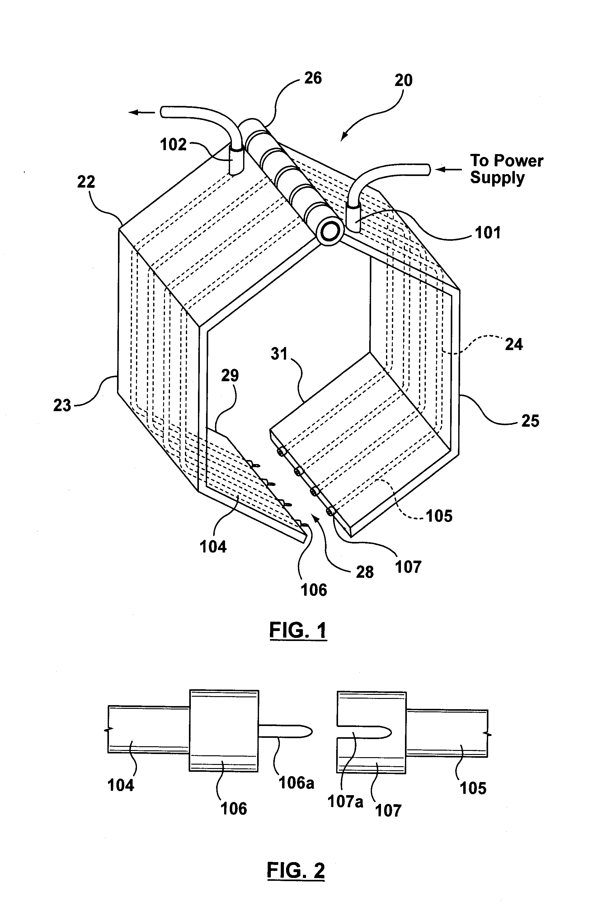
[0048]An induction apparatus with a design configuration according to FIG. 1 was manufactured, and connected to these Miller units.

[0049]The apparatus was used to heat 660 mm diameter pipe with a wall thickness of 30 mm on a joint width of 500 mm. The apparatus took 1.5 minutes to heat the steel from 23° C. to 170° C. In comparison with the traditional induction heating apparatus, this was a quarter of the time than it took with the Tesi 400 hz unit, utilizing half the power.

[0050]In addition, the apparatus had a wire cable of 7 mm in diameter and the entire apparatus, including wire coil and frame, weighed 35 kg. The combined weight of the diesel generator and the ...

example 2

[0051]A pipeline project required a Canusa heat shrink sleeve coating to be applied to the pipe joint on a 84″ diameter pipe. The pipe wall thickness was 50 mm and mainline coating was polyethylene. The exposed steel of the pipe ends was welded together, so that a joint with 300 mm exposed steel was present and the adjacent areas were coated with 5 mm thick polyethylene. The coating to be used was a Canusa GTS-80 sleeve (Shawcor Ltd., Rexdale, Canada) which required a preheat of the joint to 110° C. prior to application of the sleeve.

[0052]First an experiment was done to heat the pipe with 2 torches, each with 200,000 BTU capacity and by two people. It took 22 minutes to heat the joint steel from 23° C. to 110° C. It was determined that it would be difficult to heat such a big pipe by 2 or even 4 people with a torch flame and obtain uniform temperature and in reasonable amount of time. Thus heating of the joint with an induction coil was obviously desirable. However, traditional cla...

example 3

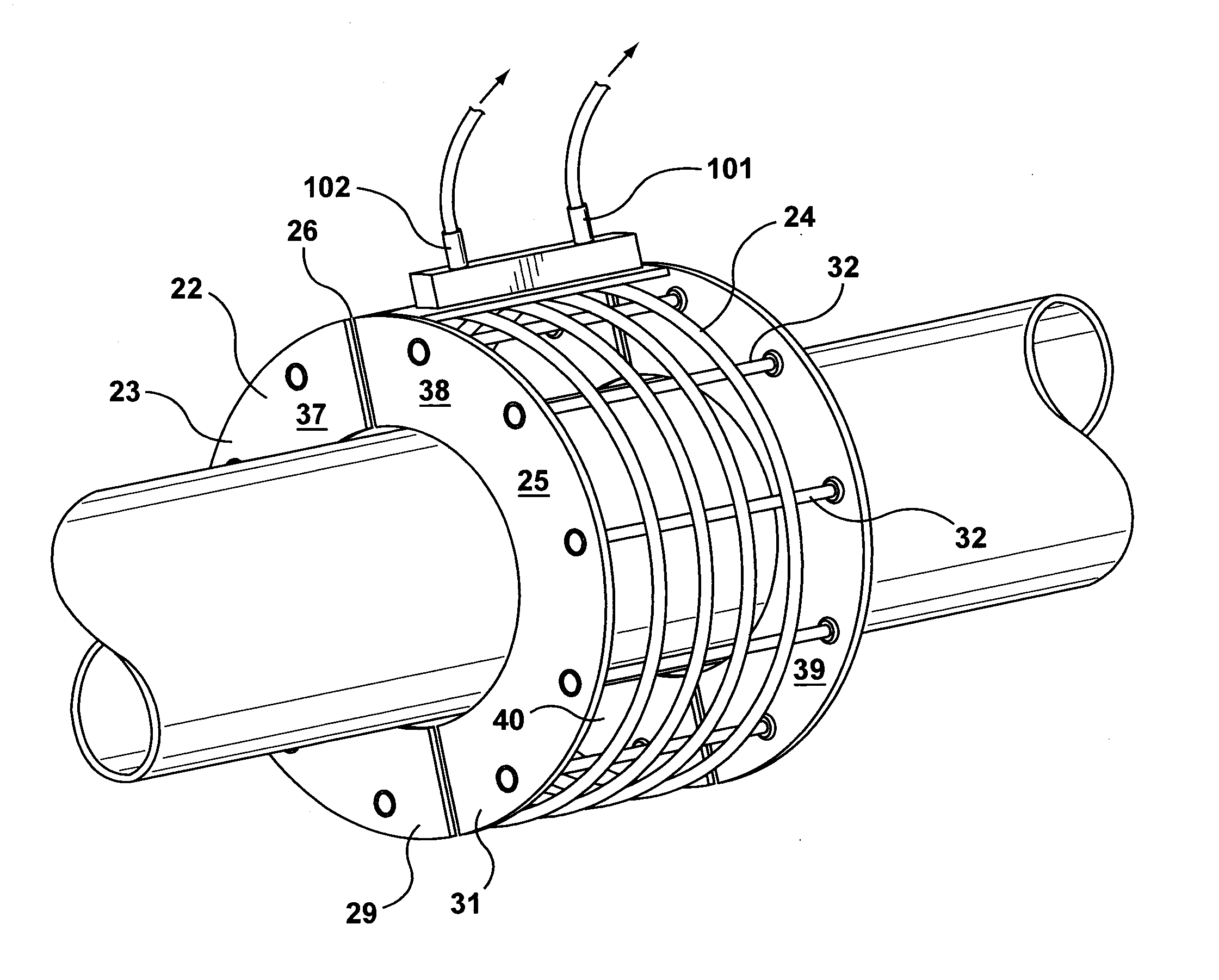
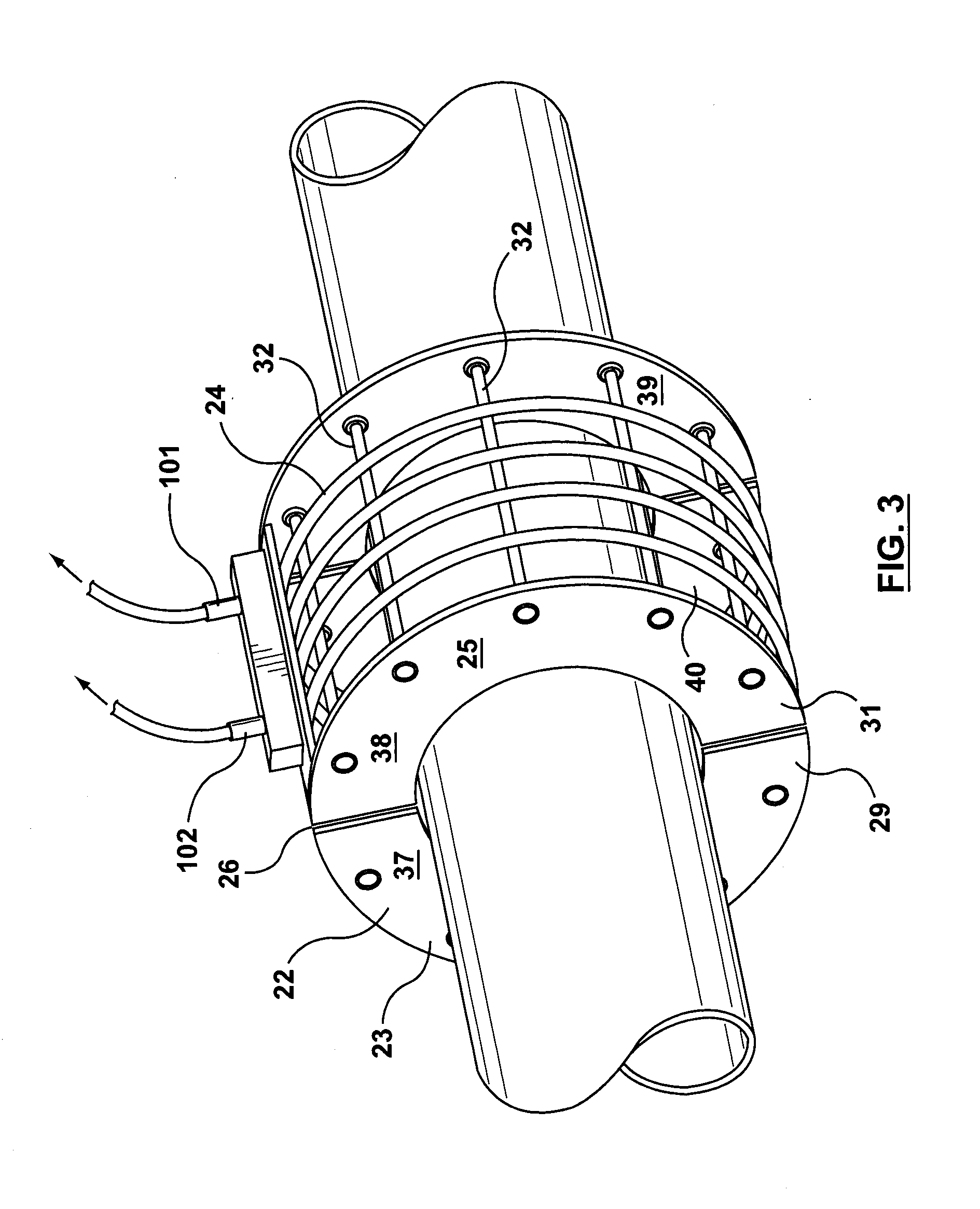
[0055]This experiment was conducted for the application of Canusa HBE liquid epoxy coating onto a pipe joint with a fusion bonded epoxy mainline coating. The installation procedure required the prewarming of the joint to 50° C. to remove the moisture, then application of the liquid epoxy with a roller, and then heating the joint to 95° C. In this application, since there is a wet liquid on the joint, the clam-shell induction coil as shown in FIG. 3 would be quite suitable, since the cables would remain elevated away from the joint surface, and the wet liquid is not disturbed. However, on large diameter pipes, such as 56″ or 84″ pipes, the use of the large clamshell coil would be considered undesirable, especially in rough terrains in the field. An induction blanket solution would be preferable.

[0056]To this end, a joint was prepared in the lab on a 48″ fusion bonded epoxy coated pipe with an exposed steel cutback of 300 mm. The joint was heated to 50° C. with the induction blanket o...


PUM

PropertyMeasurementUnit
temperatureaaaaaaaaaa
widthaaaaaaaaaa

Abstract

An induction heating apparatus for use in pre-heating pipe joints. The induction heating apparatus comprises a frame for applying around the pipe joint, and an induction heating coil made from Litz cable wires.

Description

CROSS-REFERENCE TO RELATED APPLICATION[0001]This application claims the benefit of and priority to U.S. Patent Application No. 61 / 432,852 filed Jan. 14, 2011 under the title INDUCTION HEATING APPARATUS FOR PIPELINE CONNECTIONS.[0002]The content of the above patent application is hereby expressly incorporated by reference into the detailed description hereof.FIELD OF THE INVENTION[0003]The present invention relates to an induction heating apparatus for use in heating of pipe joints and sections in pipeline connections. The induction heating apparatus comprises a frame for applying around the pipe joint, and an induction heating coil made from Litz cable wires.BACKGROUND OF THE INVENTION[0004]Usually, oil and gas pipe for pipeline construction is an inner, metal pipe, which is coated with a polymer coating. The ends of the pipe are left bare to allow the exposed ends to be welded together at a pipe joint. This pipe joint is then covered and protected. There are several different coati...

Claims


Application Information

Patent Timeline
Patent Type & Authority Applications(United States)
IPC IPC(8): F16L53/00H05B6/10F16L53/34
CPCF16L53/004H05B6/101F16L13/0272F16L58/181B29L2023/225B29C65/66B29C66/0242B29C66/1122B29C66/72321B29C66/73715B29C65/48B29C66/53241B29C66/7212F16L53/34B29C66/4322B29C66/5326B29K2995/0049B29K2309/08B29K2277/10B29K2311/10B29K2105/02
Inventor TAILOR, DILIP KUMARBRANDON, MARKSARDI, MARTINKLEJMAN, AARONMORDARSKI, JOSEPH
Owner SHAWCOR LTD
Why Eureka
Try Eureka