Transport apparatus and vacuum system

a technology of transport apparatus and vacuum system, which is applied in the direction of lighting and heating apparatus, charge manipulation, furniture, etc., can solve the problem of not being able to detect a more accurate state of the substrate, and achieve the effect of reducing the space required for the installation of detection units, reducing the size of the vacuum system, and reducing the cost required

Active Publication Date: 2013-12-26
ULVAC INC
View PDF6 Cites 4 Cited by
  • Summary
  • Abstract
  • Description
  • Claims
  • Application Information

AI Technical Summary

Benefits of technology

[0026]According to the transport apparatus and the vacuum system related to the above aspects of the present invention, it is unnecessary to provide the number of detection units corresponding to all of the first detection positions and the second detection positions that are set on the substrate at the respective first stop positions and second stop positions of the robot hand which passes the substrate with respect to the respective chambers constituting the vacuum system.
[0027]In other words, only the first detection units that correspond to the first detection positions set on the substrate are formed at the first stop positions, and only the second detection unit that corresponds to the second detection position set on the substrate is formed at the second stop positions so that the presence of the

Problems solved by technology

However, in a configuration in which only one point (for example, the center) of the substrate serves as the detection position to detect the presence of the substrate, it is possible to detect the presence of the substrate on the robot hand but it is impossible

Method used


Image

  • Transport apparatus and vacuum system
  • Transport apparatus and vacuum system
  • Transport apparatus and vacuum system

Examples


Embodiment Construction

[0042]Hereinafter, a transport apparatus and a vacuum system according to embodiments of the present invention will be described referring to the accompanying drawings. The embodiments are described using an example for further understanding the spirit of the present invention, and therefore the present invention is not limited thereto unless otherwise specified. Also, in the drawings used in the following description, the sizes of the main sections may be exaggerated for convenience and further understanding of the present invention, and the dimensional ratio of each component and the like is not necessarily to scale.

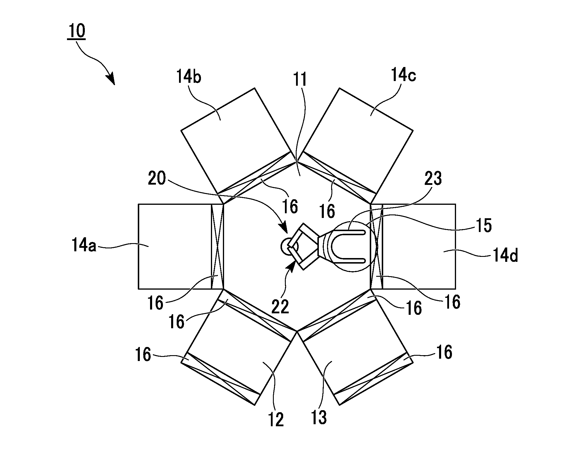
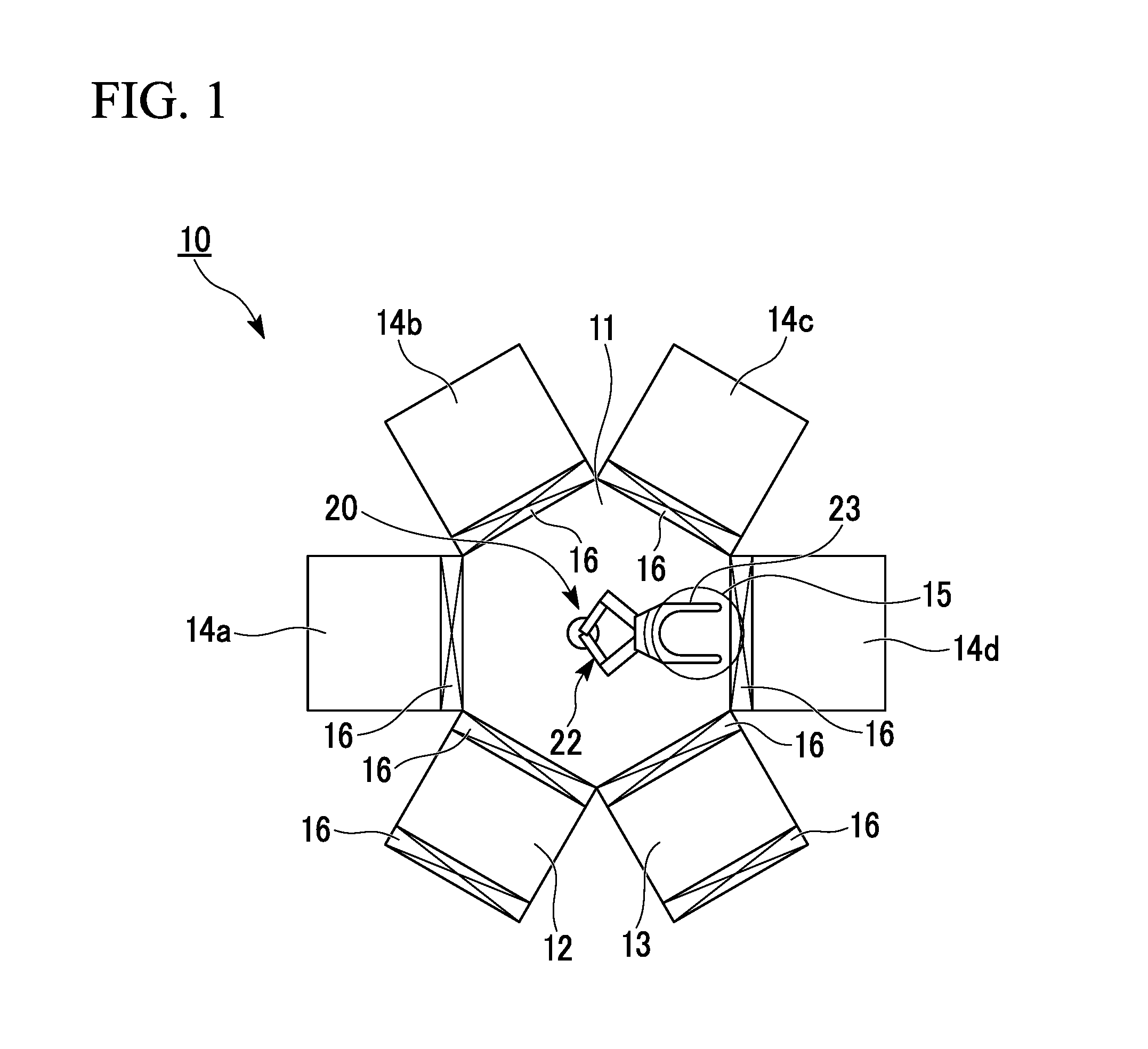
[0043]FIG. 1 is a plan view showing a configuration example of a vacuum system including a transport apparatus of an embodiment according to the present invention.

[0044]A multi chamber-type vacuum system 10 includes a transport chamber 11, and a transport apparatus (transport robot) 20 and is disposed inside the transport chamber 11. The transport apparatus 20 transpor...


PUM


Abstract

A transport apparatus that supports and moves a substrate by using a robot hand between a plurality of chambers includes a first detection unit that detects the substrate, in a first stop position of the robot hand, using a first detection position set on one surface of the substrate supported by the robot hand, and a second detection unit that detects the substrate, in a second stop position of the robot hand, using a second detection position set on the one surface of the substrate supported by the robot hand.

Description

CROSS-REFERENCE TO RELATED APPLICATION[0001]This is the U.S. National Phase Application under 35 U.S.C. §371 of International Patent Application No. PCT / JP2012 / 056844 filed Mar. 16, 2012, which designated the United States and was published in a language other than English, which claims the benefit of Japanese Patent Application No. P2011-57977 filed on Mar. 16, 2011, both of which are incorporated by reference herein.TECHNICAL FIELD [0002]The present invention relates to a transport apparatus that supports and transports a substrate by using a robot hand, and a vacuum system including the same, and more particularly, to a technology for detecting a position shift, damage, or the like of the substrate supported by the robot hand.BACKGROUND ART[0003]As a multi chamber-type vacuum system, for example, a chemical vapor deposition (CVD) apparatus with chambers such as a loading and unloading chamber and a processing chamber that surround a transport apparatus which is arranged in the ce...

Claims


Application Information

Patent Timeline
IPC IPC(8): B65G49/00
CPCB65G49/00H01L21/67259H01L21/67742H01L21/681B25J11/0095B25J13/088
Inventor FUJII, YOSHINORI
Owner ULVAC INC
Why Eureka
Try Eureka