
Resonator

a resonator and mechanical technology, applied in the field of mechanical resonators, can solve the problems of affecting the detection, too many disadvantageous effects on the operation of the system, and inapplicability of gas damping, etc., and achieve the effect of effective amplification of the detected signal

Active Publication Date: 2014-01-02
MURATA MFG CO LTD
View PDF1 Cites 7 Cited by
  • Summary
  • Abstract
  • Description
  • Claims
  • Application Information

AI Technical Summary

Benefits of technology

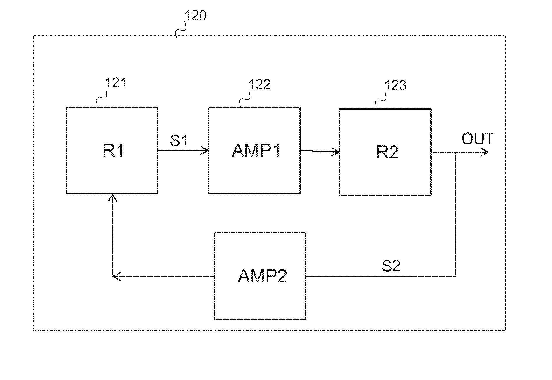
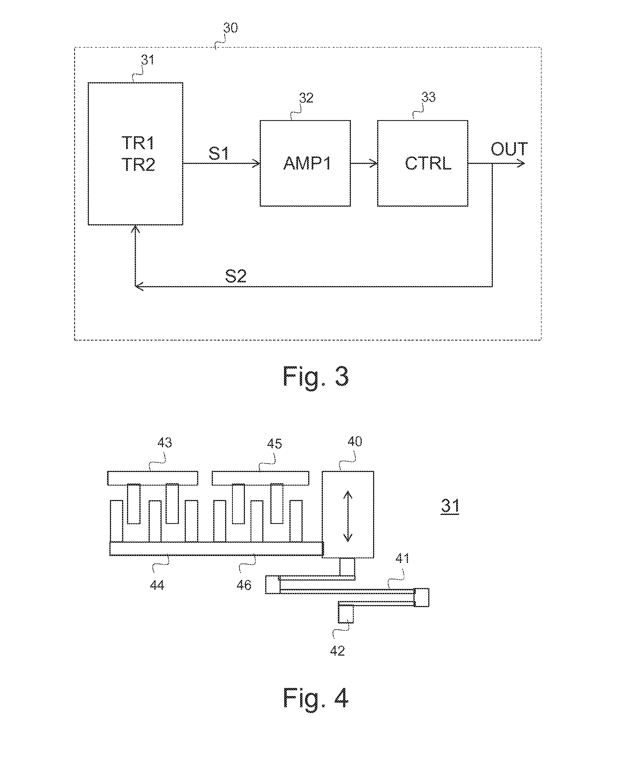
The present invention is an improvement to a damping feed-back mechanism for mechanical resonator systems. It includes a signal processing filter that adjusts the response function of the feed-back loop based on the type of filter used. This results in a stable resonator that allows effective amplification of the detected signal while avoiding unwanted oscillations in the closed feed-back loop. Active damping (also known as feed-back damping) is achievable using this improved mechanism, without causing disadvantageous effects to the operation of the system. The invention provides a more efficient and effective solution for damping motion in mechanical resonators.

Problems solved by technology

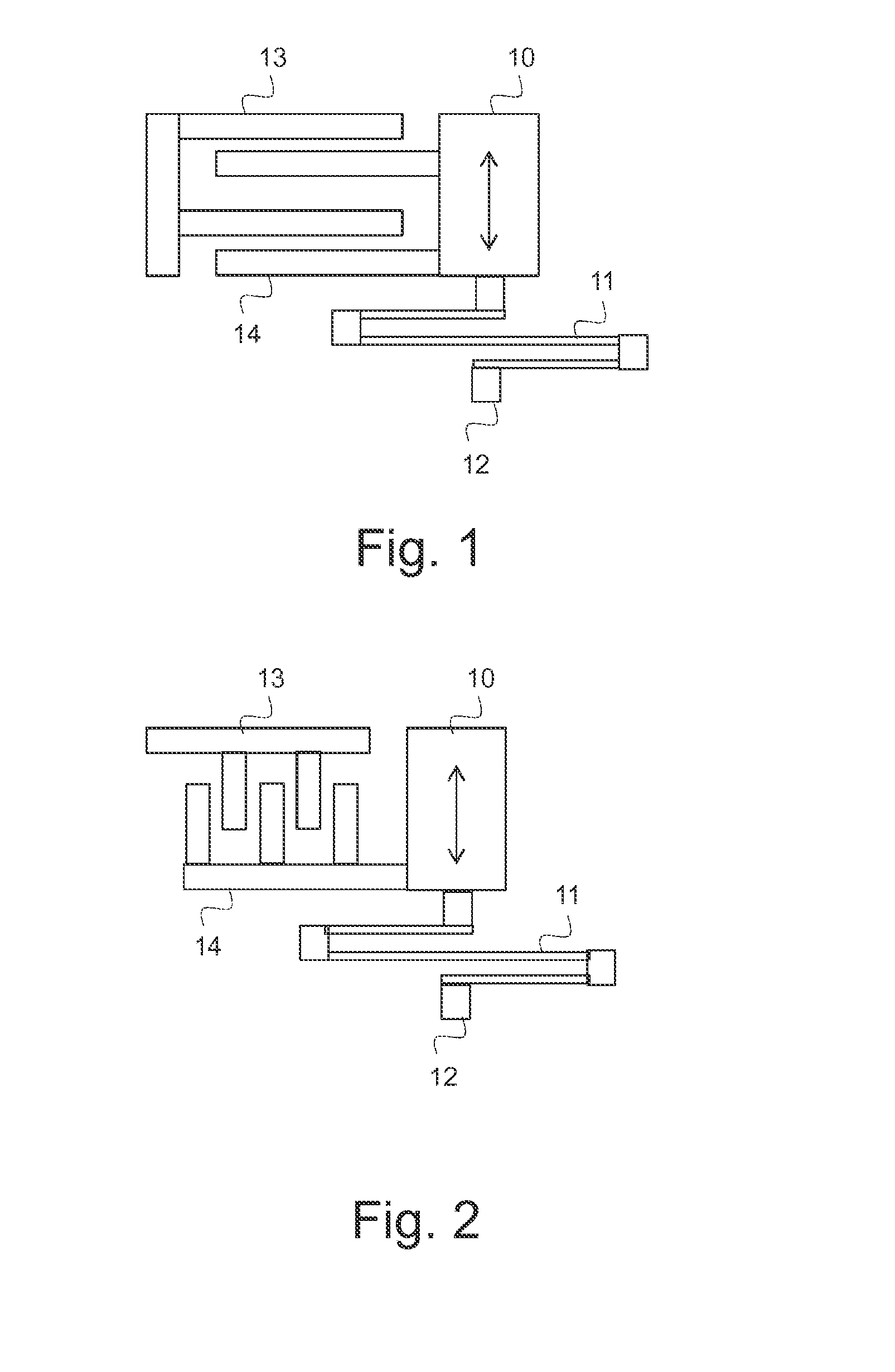
In these resonant frequencies the displacement is thus much larger than in other frequencies and in the miniaturized dimensions of MEMS structures cause overload that disturbs the detection.
A conventional method has been to use passive gas damping, but for many applications gas damping is too non-linear and causes too many disadvantageous effects to the operation of the system.
In some configurations, like vibrating gyroscopes, gas damping is not even applicable, because damping to the resonant excitation of primary vibration must be kept low.
The problem is, however, that structures are very seldom ideal and in real-life resonators there are additional mechanical resonance modes.
When the differentiator output signal is amplified to generate an appropriately high damping force, the feed-back-loop very easily starts to disruptively oscillate.

Method used


Image

  • Resonator
  • Resonator
  • Resonator

Examples


Embodiment Construction

[0029]The following embodiments are exemplary. Although the specification may refer to “an”, “one”, or “some” embodiment(s), this does not necessarily mean that each such reference is to the same embodiment(s), or that the feature only applies to a single embodiment. Single features of different embodiments may be combined to provide further embodiments.

[0030]In the following, features of the invention will be described with a simple example of a device architecture in which various embodiments of the invention may be implemented. Only elements relevant for illustrating the embodiments are described in detail. Various implementations of control elements, resonator devices and methods comprise elements that are generally known to a person skilled in the art and may not be specifically described herein.

[0031]A transducer refers here to a device that converts one form of energy to another. For example, a sensing device or a sensor refers to an apparatus or a system that detects a physi...


PUM


Abstract

A mechanical resonator with a closed feed-back damping loop is provided. Displacement in the mechanical resonator is opposed with a damping force determined by the closed feed-back loop that comprises a signal processing filter with associated phase adjustment. An oscillation-free configuration that allows high signal amplification is achieved.

Description

FIELD OF THE INVENTION[0001]The present invention relates to mechanical resonators and especially to a control element, a mechanical resonator and a method for operating a mechanical resonator, as defined in the preambles of the independent claims.BACKGROUND OF THE INVENTION[0002]Micro-Electro-Mechanical Systems, or MEMS can be defined as miniaturized mechanical and electro-mechanical systems where at least some elements have a mechanical functionality. Since MEMS devices are created with the same tools that are used to create integrated circuits, micromachines and microelectronics can be fabricated on the same piece of silicon to enable machines with intelligence.[0003]MEMS structures can be applied to quickly and accurately detect very small displacements, for example in inertial sensors. For example, in an accelerometer a mass suspended on a spring structure to the body of the device may be displaced proportional to the acceleration of the device, and these displacements of the m...

Claims


Application Information

Patent Timeline
IPC IPC(8): H02N11/00
CPCH02N11/006H03B5/30G01P15/097G01P15/13G01P15/131B81B7/008G01C19/5726G01C19/5776H03H9/02259
Inventor KUISMA, HEIKKI
Owner MURATA MFG CO LTD
Learn More