Method and system for obtaining an extended-depth-of-field volumetric image using laser scanning imaging

a laser scanning and depth of field technology, applied in the field of laser scanning imaging systems, can solve the problems of reducing the acquisition speed of thick or bulky samples, loss of temporal resolution which may not be suitable, and inability to apply laser scanning microscopy

Active Publication Date: 2014-01-09
UNIV LAVAL
View PDF7 Cites 48 Cited by
  • Summary
  • Abstract
  • Description
  • Claims
  • Application Information

AI Technical Summary

Problems solved by technology

Yet, despite the benefits of the optical sectioning capabilities and the increased spatial resolution achievable by two-photon laser scanning microscopy, the point illumination principle used in this technique reduces the acquisition speed for thick or bulk samples, since a stack of images taken at different depths must be acquired and added.
Optical sectioning thus leads to a loss of temporal resolution which may not be suitable when investigating dynamic biological processes for which temporal resolution may be more important than axial resolution.
However, it cannot be applied to laser scanning microscopy and relies on numerical post-treatment.
The depth of field extension is limited by defocus aberration, which degrades image resolution for large variations in depth.
Furthermore, in some cases, the acquired images are blurry and must be treated by digital processing before obtaining the effective resolution.
However, limitation...

Method used


Image

  • Method and system for obtaining an extended-depth-of-field volumetric image using laser scanning imaging
  • Method and system for obtaining an extended-depth-of-field volumetric image using laser scanning imaging
  • Method and system for obtaining an extended-depth-of-field volumetric image using laser scanning imaging

Examples


Embodiment Construction

[0055]In the following description, similar features in the drawings have been given similar reference numerals and in order to weigh down the figures, some elements may not be referred to on some figures if they were already identified in preceding figures. It should also be understood herein that the elements of the drawings are not necessarily drawn to scale and that the emphasis is instead being placed upon clearly illustrating the elements and structures of the present embodiments.

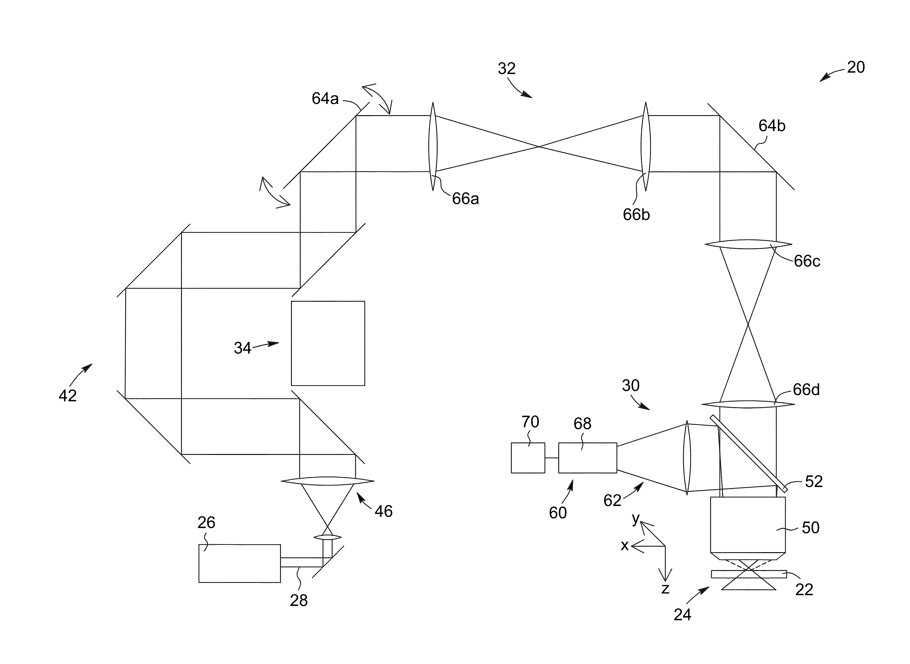
[0056]The present invention generally relates to a laser scanning imaging system and method for obtaining an image of a volume of a sample, wherein the image has an extended depth of field, that is, axial resolution, compared to standard systems and methods. The system and method according to embodiments of the present invention generally involve converting an input laser beam into an excitation non-diffracting beam in a stepwise manner, and projecting the excitation non-diffracting beam thus obtained...


PUM


Abstract

A laser scanning imaging system and method for obtaining an extended-depth-of-field image of a volume of a sample are provided. The system includes a laser module generating an input laser beam, a beam shaping module including an axicon and a Fourier-transform lens, and an imaging module including an objective lens and a detecting assembly. The axicon, Fourier-transform lens and objective lens are formed and disposed to successively convert the input laser beam into an intermediate non-diffracting beam, an intermediate annular beam, and an excitation non-diffracting beam. The excitation beam is projected onto the sample and has a depth of field and transverse resolution together defining a three-dimensional excitation region. The detecting assembly collects electromagnetic radiation from the excitation region to obtain one pixel of the extended-depth-of-field image. The system further includes a two-dimensional scanning module for scanning the excitation beam over the sample and build, pixel-by-pixel, the extended-depth-of-field image.

Description

RELATED PATENT APPLICATION[0001]This application incorporates by reference, in its entirety, and claims priority to U.S. provisional patent application Ser. No. 61 / 664,452, filed Jun. 26, 2012.FIELD OF THE INVENTION[0002]The present invention relates to the field of laser scanning imaging systems such as the type used in microscopy, and more particularly concerns a method and a system for extending and possibly adjusting the depth of field in optical laser scanning microscopy.BACKGROUND OF THE INVENTION[0003]Progress in optical microscopy has led to the emergence of a wide range of systems for fluorescence imaging of biological samples. For example, confocal [“Microscopy apparatus”, U.S. Pat. No. 3,013,467 to Minsky] and two-photon [Denk et al., “Two-Photon Laser Scanning Fluorescence Microscopy”, Science vol. 48, p. 73-76 (1990)] laser scanning fluorescence microscopes having better spatial resolution than conventional wide-field microscopy are now commonly employed for imaging nar...

Claims


Application Information

Patent Timeline
IPC IPC(8): G01N21/64
CPCG01N21/64G02B21/002G01N21/6458G02B26/101G02B26/105
Inventor THERIAULT, GABRIELLEDE KONINCK, YVESMCCARTHY, NATHALIE
Owner UNIV LAVAL
Why Eureka
Try Eureka